
Page 108 - 35_DS702_E_2014_Lightning_Protection_Guide
P. 108
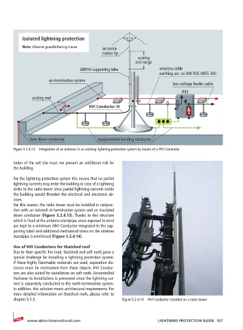
Isolated lightning protection               α α

          Note: Observe grandfathering clause  air-termi-
                                            nation tip
                                                           sealing
                                                          end range
                                   GRP/Al supporting tube           antenna cable
                                                                    earthing acc. to DIN VDE 0855-300
                      air-termination system
                                                                          low-voltage feeder cable
                                                                             RBS
               sealing end
                                      HVI Conductor III


              bare down conductor         equipotential bonding conductor
       Figure 5.2.4.13  Integration of an antenna in an existing lightning protection system by means of a HVI Conductor


       lation of the cell site must not present an additional risk for
       the building.

       For the lightning protection system this means that no partial
       lightning currents may enter the building in case of a lightning
       strike to the radio tower since partial lightning currents inside
       the building would threaten the electrical and electronic de-
       vices.
       For this reason, the radio tower must be installed in conjunc-
       tion with an isolated air-termination system and an insulated
       down conductor (Figure 5.2.4.13). Thanks to this structure
       which is fixed at the antenna standpipe, areas exposed to wind
       are kept to a minimum (HVI Conductor integrated in the sup-
       porting tube) and additional mechanical stress on the antenna
       standpipe is minimised (Figure 5.2.4.14).

       Use of HVI Conductors for thatched roof
       Due to their specific fire load, thatched and soft roofs pose a
       special challenge for installing a lightning protection system.
       If these highly flammable materials are used, separation dis-
       tances must be maintained from these objects. HVI Conduc-
       tors are also suited for installation on soft roofs. Uncontrolled
       flashover to installations is prevented since the lightning cur-
       rent is separately conducted to the earth-termination system.
       In addition, this solution meets architectural requirements. For
       more detailed information on thatched roofs, please refer to
       chapter 5.1.5.                               Figure 5.2.4.14  HVI Conductor installed on a radio tower


            www.dehn-international.com                             LIGHTNING PROTECTION GUIDE  107