
Page 110 - 35_DS702_E_2014_Lightning_Protection_Guide
P. 110
70 mm
200 mm
≤ 1000 mm Ø = 20 mm ≤ 500 mm Ø = 20 mm
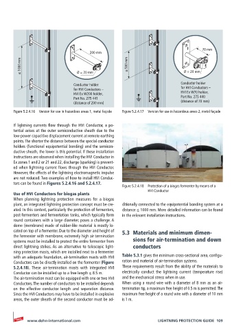
Conductor holder Conductor holder
for HVI Conductors – for HVI Conductors –
HVI Ex W200 holder, HVI Ex W70 holder,
Part No. 275 441 Part No. 275 440
(distance of 200 mm) (distance of 70 mm)
Figure 5.2.4.16 Version for use in hazardous areas 1, metal façade Figure 5.2.4.17 Version for use in hazardous areas 2, metal façade
If lightning currents flow through the HVI Conductor, a po-
tential arises at the outer semiconductive sheath due to the
low-power capacitive displacement current at remote earthing
points. The shorter the distance between the special conductor
holders (functional equipotential bonding) and the semicon-
ductive sheath, the lower is this potential. If these installation
instructions are observed when installing the HVI Conductor in
Ex zones 1 and 2 or 21 and 22, discharge (sparking) is prevent-
ed when lightning current flows through the HVI Conductor.
However, the effects of the lightning electromagnetic impulse
are not reduced. Two examples of how to install HVI Conduc-
tors can be found in Figures 5.2.4.16 and 5.2.4.17.
Figure 5.2.4.18 Protection of a biogas fermenter by means of a
HVI Conductor
Use of HVI Conductors for biogas plants
When planning lightning protection measures for a biogas
plant, an integrated lightning protection concept must be cre- ditionally connected to the equipotential bonding system at a
ated. In this context, particularly the protection of fermenters, distance ≤ 1000 mm. More detailed information can be found
post-fermenters and fermentation tanks, which typically form in the relevant installation instructions.
round containers with a large diameter, poses a challenge. A
dome (membrane) made of rubber-like material is mostly lo-
cated on top of a fermenter. Due to the diameter and height of 5.3 Materials and minimum dimen-
the fermenter with membrane, extremely high air-termination
systems must be installed to protect the entire fermenter from sions for air-termination and down
direct lightning strikes. As an alternative to telescopic light- conductors
ning protection masts, which are installed next to a fermenter
with an adequate foundation, air-termination masts with HVI Table 5.3.1 gives the minimum cross-sectional area, configu-
Conductors can be directly installed on the fermenter (Figure ration and material of air-termination systems.
5.2.4.18). These air-termination masts with integrated HVI These requirements result from the ability of the materials to
Conductor can be installed up to a free length ≤ 8.5 m. electrically conduct the lightning current (temperature rise)
The air-termination mast can be equipped with one or two HVI and the mechanical stress when in use.
Conductors. The number of conductors to be installed depends When using a round wire with a diameter of 8 mm as an air-
on the effective conductor length and separation distance. termination tip, a maximum free height of 0.5 m is permitted. The
Since the HVI Conductors may have to be installed in explosive maximum free height of a round wire with a diameter of 10 mm
areas, the outer sheath of the second conductor must be ad- is 1 m.
www.dehn-international.com LIGHTNING PROTECTION GUIDE 109