
Page 111 - 35_DS702_E_2014_Lightning_Protection_Guide
P. 111
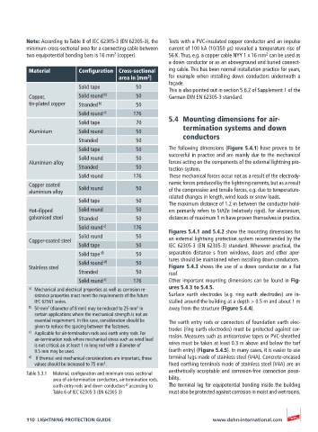
Note: According to Table 8 of IEC 62305-3 (EN 62305-3), the   Tests with a PVC-insulated copper conductor and an impulse
          minimum cross-sectional area for a connecting cable between   current of 100 kA (10/350 μs) revealed a temperature rise of
                                                                                      2
                                      2
          two equipotential bonding bars is 16 mm  (copper).  56 K. Thus, e.g. a copper cable NYY 1 x 16 mm  can be used as
                                                       a down conductor or as an aboveground and buried connect-
          Material        Configuration  Cross-sectional   ing cable. This has been normal installation practice for years,
                                                2
                                       area in [mm ]   for example when installing down conductors underneath a
                                                       façade.
                          Solid tape         50        This is also pointed out in section 5.6.2 of Supplement 1 of the
          Copper,         Solid round  b)    50        German DIN EN 62305-3 standard.
          tin-plated copper  Stranded  b)    50
                          Solid round  c)   176
                          Solid tape         70        5.4  Mounting dimensions for air-
          Aluminium       Solid round        50             termination systems and down
                          Stranded           50             conductors
                          Solid tape         50        The following dimensions (Figure 5.4.1) have proven to be
                                                       successful in practice and are mainly due to the mechanical
                          Solid round        50
          Aluminium alloy                              forces acting on the components of the external lightning pro-
                          Stranded           50        tection system.
                          Solid round       176        These mechanical forces occur not as a result of the electrody-
          Copper coated   Solid round        50        namic forces produced by the lightning currents, but as a result
          aluminium alloy                              of the compressive and tensile forces, e.g. due to temperature-
                                                       related changes in length, wind loads or snow loads.
                          Solid tape         50
                                                       The maximum distance of 1.2 m between the conductor hold-
          Hot-dipped      Solid round        50        ers primarily refers to St/tZn (relatively rigid). For aluminium,
          galvanised steel  Stranded         50        distances of maximum 1 m have proven themselves in practice.
                          Solid round  c)   176
                                                       Figures 5.4.1 and 5.4.2 show the mounting dimensions for
                          Solid round        50        an external lightning protection system recommended by the
          Copper-coated steel
                          Solid tape         50        IEC 62305-3 (EN 62305-3) standard. Wherever practical, the
                          Solid tape  d)     50        separation distance s from windows, doors and other aper-
                          Solid round  d)    50        tures should be maintained when installing down conductors.
          Stainless steel                              Figure 5.4.3 shows the use of a down conductor on a flat
                          Stranded           50        roof.
                          Solid round  c)   176        Other important mounting dimensions can be found in Fig-
          a)    Mechanical and electrical properties as well as corrosion re-  ures 5.4.3 to 5.4.5.
            sistance properties must meet the requirements of the future    Surface earth electrodes (e.g. ring earth electrodes) are in-
            IEC 62561 series.                          stalled around the building at a depth > 0.5 m and about 1 m
          b)   50 mm  (diameter of 8 mm) may be reduced to 25 mm  in   away from the structure (Figure 5.4.4).
                2
                                             2
            certain applications where the mechanical strength is not an
            essential requirement. In this case, consideration should be   The earth entry rods or connectors of foundation earth elec-
            given to reduce the spacing between the fasteners.  trodes (ring earth electrodes) must be protected against cor-
          c)    Applicable for air-termination rods and earth entry rods. For
            air-termination rods where mechanical stress such as wind load   rosion. Measures such as anticorrosive tapes or PVC-sheathed
            is not critical, an at least 1 m long rod with a diameter of    wires must be taken at least 0.3 m above and below the turf
            9.5 mm may be used.                        (earth entry) (Figure 5.4.5). In many cases, it is easier to use
          d)    If thermal and mechanical considerations are important, these   terminal lugs made of stainless steel (V4A). Concrete-encased
            values should be increased to 75 mm . 2    fixed earthing terminals made of stainless steel (V4A) are an
                                                       aesthetically acceptable and corrosion-free connection possi-
          Table 5.3.1  Material, configuration and minimum cross-sectional
                  area of air-termination conductors, air-termination rods,   bility.
                                          a)
                  earth entry rods and down conductors  according to   The terminal lug for equipotential bonding inside the building
                  Table 6 of IEC 62305-3 (EN 62305-3)  must also be protected against corrosion in moist and wet rooms.


          110  LIGHTNING PROTECTION GUIDE                            www.dehn-international.com