
Page 135 - 35_DS702_E_2014_Lightning_Protection_Guide
P. 135
can be considered to be an electrical insulator downstream of or below the ground water level by means of pressure-water-
the water penetration area. Thus, the foundation earth elec- tight bushings.
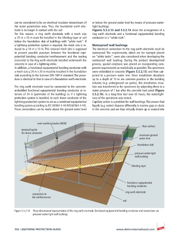
trode is no longer in contact with the soil. Figures 5.5.2.13 and 5.5.2.14 show the arrangement of a
For this reason, a ring earth electrode with a mesh size ring earth electrode and a functional equipotential bonding
≤ 20 m x 20 m must be installed in the blinding layer or soil conductor in a “white tank”.
below the foundation slab of buildings with “white tank”. If
a lightning protection system is required, the mesh size is re- Waterproof wall bushings
duced to ≤ 10 m x 10 m. This reduced mesh size is supposed The electrical connection to the ring earth electrode must be
to prevent possible puncture between the functional equi- waterproof. The requirements, which are for example placed
potential bonding conductor / reinforcement and the sealing on “white tanks”, were also considered when developing the
(concrete) to the ring earth electrode installed underneath the waterproof wall bushing. During the product development
concrete in case of a lightning strike. process, special emphasis was placed on incorporating com-
In addition, a functional equipotential bonding conductor with ponent requirements as realistically as possible. The specimens
a mesh size ≤ 20 m x 20 m must be installed in the foundation were embedded in concrete (Figure 5.5.2.15) and then sub-
slab according to the German DIN 18014 standard. The proce- jected to a pressure water test. Since installation situations
dure is identical to that in case of a foundation earth electrode. up to a depth of 10 m are common practice in the building
industry (e.g. underground car parks), this installation situa-
The ring earth electrode must be connected to the concrete- tion was transferred to the specimens by subjecting them to a
embedded functional equipotential bonding conductor at in- water pressure of 1 bar after the concrete had cured (Figure
tervals of 20 m (perimeter of the building) or, if a lightning 5.5.2.16). In a long-time test over 65 hours, the watertight-
protection system is installed, to each down conductor of the ness of the specimens was tested.
lightning protection system to act as a combined equipotential Capillary action is a problem for wall bushings. This means that
bonding system according to IEC 60364-4-44 (HD 60364-4-44). liquids (e.g. water) disperse differently in narrow gaps or ducts
These connections can be made above the ground water level in the concrete and are thus virtually drawn up or soaked into
main earthing busbar (MEB)
floor surface
terminal lug for
the down conductor
maximum ground
water level
foundation slab
pressure-water-tight
wall bushing
blinding layer
functional equipotential
bonding conductor
ring earth electrode
connection to
the reinforcement
soil
Figure 5.5.2.14 Three-dimensional representation of the ring earth electrode, functional equipotential bonding conductor and connections via
pressure-water-tight wall bushings
134 LIGHTNING PROTECTION GUIDE www.dehn-international.com