
Page 130 - 35_DS702_E_2014_Lightning_Protection_Guide
P. 130
pose. The earth electrode must be in contact with the soil for 5.5.2 Earth-termination systems, foundation
at least 80 % of its total length to ensure that a type B earth earth electrodes and foundation earth
electrode can be used as a base for calculating the separa- electrodes for special structural measures
tion distance. The minimum lengths of type B earth electrodes
depend on the class of LPS. In case of classes of LPS I and II, Foundation earth electrodes – Type B earth
the minimum earth electrode length also depends on the soil electrodes
resistivity (Figure 5.5.1.1). DIN 18014 (German standard) specifies the requirements for
The mean radius r of the area encircled by a type B earth elec- foundation earth electrodes of new buildings.
trode must be not less than the specified minimum length l 1 . Many national and international standards prefer founda-
To determine the mean radius r, the area under consideration tion earth electrodes because, when properly installed, they
is transferred into an equivalent circular area and the radius is are embedded in concrete on all sides and are thus corrosion-
determined as shown in Figures 5.5.1.2 and 5.5.1.3. resistant. The hygroscopic characteristics of concrete typically
ensure a sufficiently low earth resistance.
Sample calculation: The foundation earth electrode must be installed as a closed
If the required value of l 1 is greater than the value of r cor- ring in the strip foundation or floor slab (Figure 5.5.2.1) and
responding to the structure, further radial or vertical earth thus primarily serves the purpose of functional equipotential
electrodes (or inclined earth electrodes) must be added whose bonding. The division into meshes ≤ 20 m x 20 m and the
relevant lengths l r (radial / horizontal) and l v (vertical) result connectors required to the outside to connect the down con-
from the following equations: ductors of the external lightning protection system and to the
inside for equipotential bonding must be considered (Figure
l = l r
r 1 5.5.2.2). According to DIN 18014, the installation of the foun-
dation earth electrode is an electrical measure and must there-
l r
l = 1
v
2
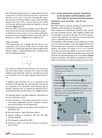
Foundation earth electrode
The number of additional earth electrodes must not be less – Round wire (Ø 10 mm) or strip (30 mm x 3.5 mm), St/tZn
than the number of down conductors, but at least two. These – Concrete cover of at least 5 m
additional earth electrodes should be connected to the ring – Closed ring
earth electrode so as to be spaced equally around the perim- – Connection to the reinforcement at intervals of 2 m by means
eter. of a clamp
Terminal lug to main earthing busbar and
If additional earth electrodes are to be connected to the
foundation earth electrode, the earth electrode material and terminal lugs for the external lightning protection system
the connection to the foundation earth electrode must be with SV clamp at least 1.5 m long, easily identifiable
observed. Stainless steel, e.g. material No. AISI/ASTM 316 Ti, – Round wire, StSt, e.g. mat. No. AISI/ASTM 316 Ti (V4A), 10 mm
should be preferably used (see chapter 5.5.2, Figure 5.5.2.1). – Strip, StSt, e.g. mat. No. AISI/ASTM 316 Ti (V4A), 30 x 3.5 mm
– Round wire, StZn, Ø 10 mm, with plastic sheath
The following systems may place additional requirements on – Fixed earthing terminal
the earth-termination system:
¨ Electrical systems – Disconnection requirements of the rel-
evant system configuration (TN, TT, IT systems) in accord- ... 2 m ...
ance with IEC 60364-4-41 (HD 60364-4-41)
¨ Equipotential bonding in accordance with IEC60364-5-54
(HD 60364-5-54)
¨ Electronic systems – Data information systems
¨ Antenna earthing in accordance with DIN VDE 0855 Higher earth electrode
(German standard) cross-sections may be re-
¨ Electromagnetic compatibility (EMC) quired for buildings with
transformer stations.
¨ Transformer station in or near the structure in accordance
with EN 50522 Figure 5.5.2.1 Foundation earth electrode with terminal lug
www.dehn-international.com LIGHTNING PROTECTION GUIDE 129