
Page 131 - 35_DS702_E_2014_Lightning_Protection_Guide
P. 131
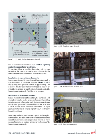
...  2 m ...  additional connecting cable
                                 for forming meshes
                                 ≤ 20 x 20 m


           ≤ 20 m


                   ≤ 20 m        15 m
                                                       Figure 5.5.2.3  Foundation earth electrode
               terminal lug      Recommendation: Several
               e.g. according to class of   terminal lugs e.g. in every
               LPS III at intervals of 15 m  technical equipment room

          Figure 5.5.2.2  Mesh of a foundation earth electrode

          fore be carried out or supervised by a certified lightning
          protection specialist or electrician.
          The question of how to install the foundation earth electrode
          depends on the measure required to ensure that the founda-
          tion earth electrode is embedded in concrete on all sides.
          Installation in non-reinforced concrete
          Spacers must be used in non-reinforced foundations such as
          strip foundations of residential buildings (Figure 5.5.2.3).
          Only by using these spacers at intervals of approximately 2 m it
          is ensured that the foundation earth electrode is “raised” and   Figure 5.5.2.4  Foundation earth electrode in use
          embedded in concrete (at least 5 cm) on all sides to protect the
          foundation earth electrode (St/tZn) against corrosion.

          Installation in reinforced concrete
          In case of closed reinforced foundations, the foundation earth
          electrode is installed on the lowest reinforcement layer. When
          installed properly, a foundation earth electrode made of round
          or strip steel (galvanised) is covered by concrete by at least
          5 cm on all sides and is thus corrosion-resistant. The hygro-
          scopic characteristics of concrete typically ensure a sufficiently
          low earth resistance.

          When using steel mats, reinforcement cages or reinforcing bars
          in foundations, the foundation earth electrode should be con-
          nected to these natural iron components at intervals of 2 m by
          means of clamping or welding to improve the function of the
          foundation earth electrode.                  Figure 5.5.2.5  Fixed earthing terminal


          130  LIGHTNING PROTECTION GUIDE                            www.dehn-international.com