
Page 142 - 35_DS702_E_2014_Lightning_Protection_Guide
P. 142
600 003) (Figure 5.5.4.2). When using this hammer frame ¨ The coupling joints of galvanised earth rods are also hot-
with a striking tool, the striking energy is constantly applied to dip galvanised
the striking surface of the earth rod via the hammer insert. This ¨ Easy to store and transport since the individual rods are
is not ensured if no hammer frame is used and the striking tool 1.5 or 1 m long. The smaller individual rod length of
is operated by hand. Therefore, it is not advisable to drive earth 1 m is particularly designed for subsequent installation
rods more than 6 m into medium or heavy grounds without e.g. into buildings (working height including vibration
using a hammer frame. hammer).
DEHN earth rods have the following benefits:
¨ Special coupling: no increase in diameter so that the earth 5.5.5 Earth electrodes in rocky ground
rod is in direct contact with the soil across its full length In rocky or stony ground, surface earth electrodes such as ring
¨ Self-closing coupling when driving the rods into the soil or radial earth electrodes are often the only way to create
an earth-termination system. When installing the earth elec-
¨ Easy to drive in by means of a vibration hammer or manual
beetle trodes, the strip or round material is laid on the stony or rocky
ground. The earth electrode should be covered with gravel, wet
¨ Constant resistance values are achieved since the earth mix aggregate or the like and should be made of stainless steel
rods penetrate through soil layers which are unaffected by (V4A), e.g. material No. AISI/ASTM 316 Ti. The clamping points
seasonal changes in moisture and temperature should be installed with care and should be protected against
¨ High corrosion resistance as a result of hot-dip galvanising corrosion. They should consist of a similar corrosion-proof ma-
(thickness of the zinc coating: 70 μm) terial as the earth electrode.
¨ Earth rods made of galvanised steel and stainless steel
(V4A), e.g. material No. AISI/ASTM 316 Ti, are available
5.5.6 Meshed earth-termination systems
An earth-termination system can fulfil a variety of func-
tions.
The purpose of protective earthing is to safely connect electri-
cal installations and equipment to the earth potential and to
protect human life and property in the event of an electrical
fault.
Lightning protection earthing ensures that the current from the
down conductors is safely discharged to the ground.
The function of functional earthing is to ensure safe and fault-
less operation of electrical and electronic systems.
The earth-termination system of a structure must be used for
all earthing tasks, in other words the earth-termination system
fulfils all earthing tasks. If this is not the case, potential differ-
ences can occur between the installations earthed on different
earth-termination systems.
In practice, “clean earth” used to be separated from light-
ning protection and protective earth for functionally earthing
electronic equipment. This is extremely unfavourable and can
even be dangerous. In the event of lightning effects, extremely
high potential differences up to some 100 kV occur in the
earth-termination system. This can lead to the destruction of
electronic equipment and life hazard. Therefore, IEC 62305-3
(EN 62305-3) and IEC 62305-4 (EN 62305-4) require consist-
ent equipotential bonding within a structure.
Electronic equipment within a structure can be earthed ra-
dially, centrally or by meshes. A meshed earth-termination
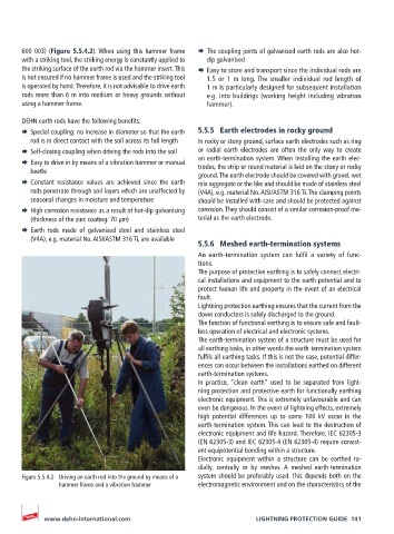
Figure 5.5.4.2 Driving an earth rod into the ground by means of a system should be preferably used. This depends both on the
hammer frame and a vibration hammer electromagnetic environment and on the characteristics of the
www.dehn-international.com LIGHTNING PROTECTION GUIDE 141