
Page 152 - 35_DS702_E_2014_Lightning_Protection_Guide
P. 152
(e.g. concrete, clinker, thermal insulation composite system) reference point for determining the length l. High buildings make
(Figure 5.6.4). Thus, it cannot be assumed that there is an air it more difficult to maintain the required separation distances.
clearance between the two materials. The total material factor
for this constellation is accordingly lower: Partitioning coefficient k c
The factor k c considers the current distribution in the down-
(0.35m 0.5+ 0.08m 0 + 0.12m 0.5) conductor system of the external lightning protection system.
k = Different calculation formulas for k c are specified in the stand-
mtotal 0.55m
ard. To be able to achieve separation distances for high build-
k m total = 0.427 ings which are feasible in practice, it is recommended to install
ring conductors. This intermeshing balances the current flow,
In general, it is advisable to assume the worst case and to use thus reducing the required separation distance.
a material factor k m = 0.5. The potential difference between the installations of the build-
ing and the down conductors is equal to zero near the surface
of the earth and grows in relation with the height. This poten-
Length l
The length l (Figure 5.6.4) is the actual length along the air- tial gradient area can be imagined as a cone standing on its tip
(Figure 5.6.1). Thus, the separation distance to be maintained
termination system or down conductor from the point at which is greatest at the tip of the building or on the roof surface
the separation distance is to be determined to the next light- and becomes less towards the earth-termination system. This
ning equipotential bonding level (zero potential level) or the means that the distance from the down conductors may have
earth-termination system. to be calculated several times with a different length l.
Each building with a lightning equipotential bonding system
has an equipotential surface of the foundation earth electrode The calculation of the partitioning coefficient k c often proves
or earth electrode near the surface of the earth. This surface is to be difficult due to the different structures.
the reference plane for determining the length l.
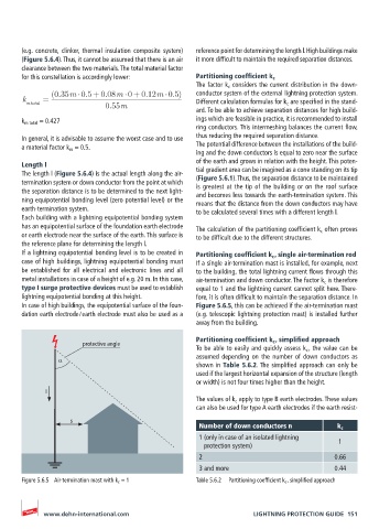
If a lightning equipotential bonding level is to be created in Partitioning coefficient k c , single air-termination rod
case of high buildings, lightning equipotential bonding must If a single air-termination mast is installed, for example, next
be established for all electrical and electronic lines and all to the building, the total lightning current flows through this
metal installations in case of a height of e.g. 20 m. In this case, air-termination and down conductor. The factor k c is therefore
type I surge protective devices must be used to establish equal to 1 and the lightning current cannot split here. There-
lightning equipotential bonding at this height. fore, it is often difficult to maintain the separation distance. In
In case of high buildings, the equipotential surface of the foun- Figure 5.6.5, this can be achieved if the air-termination mast
dation earth electrode / earth electrode must also be used as a (e.g. telescopic lightning protection mast) is installed further
away from the building.
Partitioning coefficient k c , simplified approach
protective angle
To be able to easily and quickly assess k c , the value can be
α assumed depending on the number of down conductors as
shown in Table 5.6.2. The simplified approach can only be
used if the largest horizontal expansion of the structure (length
or width) is not four times higher than the height.
I
The values of k c apply to type B earth electrodes. These values
can also be used for type A earth electrodes if the earth resist-
s
Number of down conductors n k c
1 (only in case of an isolated lightning
protection system) 1
2 0.66
3 and more 0.44
Figure 5.6.5 Air-termination mast with k c = 1 Table 5.6.2 Partitioning coefficient k c , simplified approach
www.dehn-international.com LIGHTNING PROTECTION GUIDE 151