
Page 157 - 35_DS702_E_2014_Lightning_Protection_Guide
P. 157
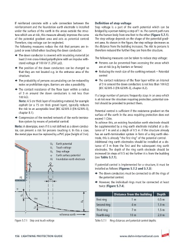
If reinforced concrete with a safe connection between the   Definition of step voltage
          reinforcement and the foundation earth electrode is installed   Step voltage is a part of the earth potential which can be
          under the surface of the earth in the areas outside the struc-  bridged by a person taking a step of 1 m. The current path runs
          ture which are at risk, this measure already improves the curve   via the human body from one foot to the other (Figure 5.7.1).
          of the potential gradient area and acts as potential control.   The step voltage depends on the shape of the potential gradi-
          Therefore, step voltage can be neglected.    ent area. As shown in the figure, the step voltage decreases as
          The following measures reduce the risk that persons are in-  the distance from the building increases. The risk to persons is
          jured or even killed when touching the down conductor:  therefore reduced the further they are from the structure.
          ¨  The down conductor is covered with insulating material (at
            least 3 mm cross-linked polyethylene with an impulse with-  The following measures can be taken to reduce step voltage:
            stand voltage of 100 kV (1.2/50 μs)).      ¨  Persons can be prevented from accessing the areas which
          ¨  The position of the down conductors can be changed so   are at risk (e.g. by barriers or fences)
            that they are not located e.g. in the entrance area of the   ¨  Reducing the mesh size of the earthing network – Potential
            structure.                                   control
          ¨  The probability of persons accumulating can be reduced by   ¨  The contact resistance of the floor layer within an interval
            notes or prohibition signs. Barriers are also a possibility.  of 3 m around the down conductors is not less than 100 kΩ
          ¨  The contact resistance of the floor layer within a radius   (IEC 62305-3 (EN 62305-3), chapter 8.2).
            of 3 m around the down conductors is not less than
            100 kΩ.                                    If a large number of persons frequently stays in an area which
            Note: A 5 cm thick layer of insulating material, for example   is at risk near the structure requiring protection, potential con-
            asphalt (or a 15 cm thick gravel layer), typically reduces   trol should be provided to protect them.
            the risk to an acceptable level (IEC 62305-3 (EN 62305-3),
            chapter 8.1).                              Potential control is sufficient if the resistance gradient on the
                                                       surface of the earth in the area requiring protection does not
          ¨  Compression of the meshed network of the earth-termina-  exceed 1 Ω/m.
            tion system by means of potential control.  To achieve this, an existing foundation earth electrode should
          Note: A downpipe, even if it is not defined as a down conduc-  be supplemented by a ring earth electrode installed at a dis-
          tor, can present a risk for persons touching it. In this a case,   tance of 1 m and at a depth of 0.5 m. If the structure already
          the metal pipe must be replaced by a PVC pipe (height of 3 m).  has an earth-termination system in form of a ring earth elec-
                                                       trode, this is already “the first ring” of the potential control.
                                                       Additional ring earth electrodes should be installed at a dis-
                              U E   Earth potential    tance  of  3  m  from  the  first  and  the  subsequent  ring  earth
                              U t    Touch voltage     electrodes. The depth of the ring earth electrode should be
                              U S   Step voltage       increased (in steps of 0.5 m) the further it is from the building
                              ϕ   Earth surface potential  (see Table 5.7.1).
                              FE  Foundation earth electrode
                                                       If potential control is implemented for a structure, it must be
                                                       installed as follows (Figures 5.7.2 and 5.7.3):
                                                       ¨  The down conductors must be connected to all the rings of
            FE                                           the potential control.
                             1 m
                                                       ¨  However, the individual rings must be connected at least
                                                         twice (Figure 5.7.4).
           ϕ
                                                                  Distance from the building  Depth
              U t
                    ϕ FE                                First ring          1 m            0.5 m
                                                U E
                                                        Second ring         4 m            1.0 m
                     U S
                                                        Third ring          7 m            1.5 m
                                   reference earth      Fourth ring        10 m            2.0 m
          Figure 5.7.1  Step and touch voltage         Table 5.7.1  Ring distances and potential control depths


          156  LIGHTNING PROTECTION GUIDE                            www.dehn-international.com