
Page 153 - 35_DS702_E_2014_Lightning_Protection_Guide
P. 153
c
c
h
h
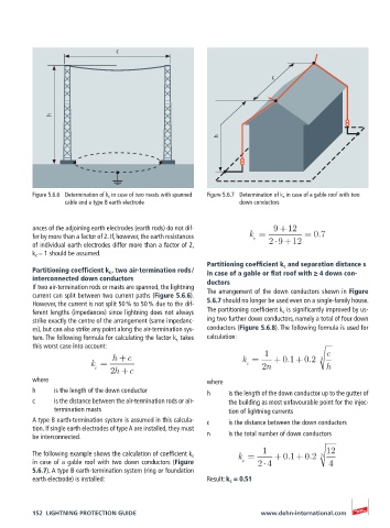
Figure 5.6.6 Determination of k c in case of two masts with spanned Figure 5.6.7 Determination of k c in case of a gable roof with two
cable and a type B earth electrode down conductors
ances of the adjoining earth electrodes (earth rods) do not dif- 9 +12
fer by more than a factor of 2. If, however, the earth resistances k = = 0.7
c
of individual earth electrodes differ more than a factor of 2, 2 9 +12
k c = 1 should be assumed.
Partitioning coefficient k c and separation distance s
Partitioning coefficient k c , two air-termination rods / in case of a gable or flat roof with ≥ 4 down con-
interconnected down conductors ductors
If two air-termination rods or masts are spanned, the lightning
current can split between two current paths (Figure 5.6.6). The arrangement of the down conductors shown in Figure
However, the current is not split 50 % to 50 % due to the dif- 5.6.7 should no longer be used even on a single-family house.
ferent lengths (impedances) since lightning does not always The partitioning coefficient k c is significantly improved by us-
strike exactly the centre of the arrangement (same impedanc- ing two further down conductors, namely a total of four down
es), but can also strike any point along the air-termination sys- conductors (Figure 5.6.8). The following formula is used for
tem. The following formula for calculating the factor k c takes calculation:
this worst case into account:
h +c k = 1 + 0.1+ 0.2 3 c
k = c
c 2h +c 2n h
where where
h is the length of the down conductor h is the length of the down conductor up to the gutter of
c is the distance between the air-termination rods or air- the building as most unfavourable point for the injec-
termination masts tion of lightning currents
A type B earth-termination system is assumed in this calcula- c is the distance between the down conductors
tion. If single earth electrodes of type A are installed, they must
be interconnected. n is the total number of down conductors
1 12
The following example shows the calculation of coefficient k c k = + 0.1+ 0.2 3
in case of a gable roof with two down conductors (Figure c 2 4 4
5.6.7). A type B earth-termination system (ring or foundation
earth electrode) is installed: Result: k c ≈ 0.51
152 LIGHTNING PROTECTION GUIDE www.dehn-international.com