
Page 154 - 35_DS702_E_2014_Lightning_Protection_Guide
P. 154
The equation is an approximation for spatial structures and for The distances of the down conductors are based on the class of
n ≥ 4. The values of h and c are assumed to be up to 20 m at a LPS (Table 6 of IEC 62305-3 (EN 62305-3)). A deviation of +/–
distance of 3 m. If internal down conductors are installed, they 20 % is acceptable. Thus, the distance c defines the largest dis-
should be considered in the number n. tance between the symmetrically arranged down conductors.
In case of flat-roofed structures, the partitioning coefficient k c
is calculated as follows. A type B earth electrode arrangement Detailed approach for determining the separation
is a precondition in this case (Figure 5.6.9): distance s
In addition to the possibilities described above for determining
1 c
k = + 0.1+ 0.2 3 the partitioning coefficient k c and the separation distance s,
c 2n h a more detailed calculation method can be used. In case of
buildings with a meshed lightning protection system, the cur-
where rent is split evenly due to the high number of current paths
h is the distance or height between ring conductors formed by conductors on the flat roof and down conductors.
c is the distance between a down conductor and the This has a positive effect on the separation distance. If a roof-
next down conductor mounted structure as shown in Figure 5.6.10 is installed on
n is the total number of down conductors a building, the detailed calculation method allows to calculate
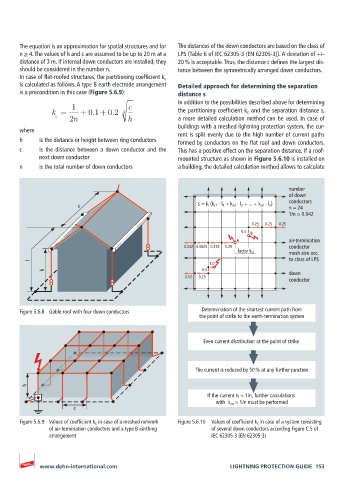
number
of down
c s = k i (k c1 ⋅ l 1 + k c2 ⋅ l 2 + ... + k cn ⋅ l n ) conductors
n = 24
1/n = 0.042
0.25 0.25 0.25
0.5 B
A air-termination
0.042 0.0625 0.125 0.25 conductor
mesh size acc.
factor k c1
to class of LPS
l
1.0
h 0.5 down
0.12 0.25
conductor
Figure 5.6.8 Gable roof with four down conductors Determination of the shortest current path from
the point of strike to the earth-termination system
Even current distribution at the point of strike
The current is reduced by 50 % at any further junction
h
If the current is < 1/n, further calculations
with k cn = 1/n must be performed
c
Figure 5.6.9 Values of coefficient k c in case of a meshed network Figure 5.6.10 Values of coefficient k c in case of a system consisting
of air-termination conductors and a type B earthing of several down conductors according Figure C.5 of
arrangement IEC 62305-3 (EN 62305-3)
www.dehn-international.com LIGHTNING PROTECTION GUIDE 153