
Page 155 - 35_DS702_E_2014_Lightning_Protection_Guide
P. 155
¨ k c = 1 from the point of proximity to the first node.
Between the first node and the next node, k c2 depends on the
number of conductors:
¨ k c = 0.5 in case of two conductors
¨ k c = 0.33 in case of three conductors
air-termination rod ¨ k c = 0.25 in case of four conductors
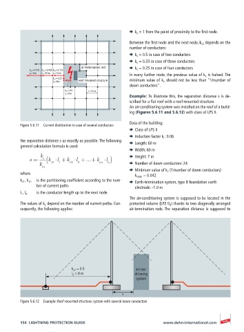
k c6 = 0.042 k c5 = 0.063 k c4 = 0.125
l 6 = 8 m l 5 = 10 m l 4 = 10 m
In every further node, the previous value of k c is halved. The
k c3 = 0.25 minimum value of k c should not be less than “1/number of
l 3 = 4 m roof-mounted structure
down conductors”.
k c2 = 0.5 l = 10 m
l 2 = 8 m
Example: To illustrate this, the separation distance s is de-
scribed for a flat roof with a roof-mounted structure.
An air-conditioning system was installed on the roof of a build-
ing (Figures 5.6.11 and 5.6.12) with class of LPS II.
Data of the building:
Figure 5.6.11 Current distribution in case of several conductors
¨ Class of LPS II
¨ Induction factor k i : 0.06
the separation distance s as exactly as possible. The following ¨ Length: 60 m
general calculation formula is used:
¨ Width: 60 m
k ¨ Height: 7 m
s = i k ( l +k l +...+k l )
k c1 1 c2 2 cn n ¨ Number of down conductors: 24
m
¨ Minimum value of k c (1/number of down conductors)
where k cmin = 0.042
k c1 , k cn is the partitioning coefficient according to the num- ¨ Earth-termination system, type B foundation earth
ber of current paths electrode: –1.0 m
l 1 , l n is the conductor length up to the next node
The air-conditioning system is supposed to be located in the
The values of k c depend on the number of current paths. Con- protected volume (LPZ 0 B ) thanks to two diagonally arranged
sequently, the following applies: air-termination rods. The separation distance is supposed to
k c2 = 0.5 air-con-
l 2 = 8 m ditioning
system
s
Figure 5.6.12 Example: Roof-mounted structure; system with several down conductors
154 LIGHTNING PROTECTION GUIDE www.dehn-international.com