
Page 17 - 35_DS702_E_2014_Lightning_Protection_Guide
P. 17
leader
leader
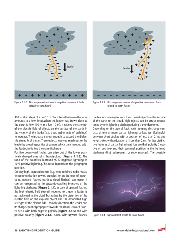
Figure 2.1.2 Discharge mechanism of a negative downward flash Figure 2.1.3 Discharge mechanism of a positive downward flash
(cloud-to-earth flash) (cloud-to-earth flash)
300 km/h in steps of a few 10 m. The interval between the jerks the leaders propagate from the exposed object on the surface
amounts to a few 10 µs. When the leader has drawn close to of the earth to the cloud, high objects can be struck several
the earth (a few 100 m to a few 10 m), it causes the strength times by one lightning discharge during a thunderstorm.
of the electric field of objects on the surface of the earth in Depending on the type of flash, each lightning discharge con-
the vicinity of the leader (e.g. trees, gable ends of buildings) sists of one or more partial lightning strikes. We distinguish
to increase. The increase is great enough to exceed the dielec- between short strokes with a duration of less than 2 ms and
tric strength of the air. These objects involved reach out to the long strokes with a duration of more than 2 ms. Further distinc-
leader by growing positive streamers which then meet up with tive features of partial lightning strikes are their polarity (nega-
the leader, initiating the main discharge. tive or positive) and their temporal position in the lightning
Positive downward flashes can arise out of the lower, posi- discharge (first, subsequent or superimposed). The possible
tively charged area of a thundercloud (Figure 2.1.3). The
ratio of the polarities is around 90 % negative lightning to
10 % positive lightning. This ratio depends on the geographic
location.
On very high, exposed objects (e.g. wind turbines, radio masts,
telecommunication towers, steeples) or on the tops of moun-
tains, upward flashes (earth-to-cloud flashes) can occur. It
can be recognised by the upwards-reaching branches of the
lightning discharge (Figure 2.1.4). In case of upward flashes,
the high electric field strength required to trigger a leader is
not achieved in the cloud, but rather by the distortion of the
electric field on the exposed object and the associated high
strength of the electric field. From this location, the leader and
its charge channel propagate towards the cloud. Upward flash-
es occur with both negative polarity (Figure 2.1.5) and with
positive polarity (Figure 2.1.6). Since, with upward flashes, Figure 2.1.4 Upward flash (earth-to-cloud flash)
16 LIGHTNING PROTECTION GUIDE www.dehn-international.com