
Page 21 - 35_DS702_E_2014_Lightning_Protection_Guide
P. 21
2.3 Steepness of the lightning current formation of a lightning channel, the lightning current rise in
rise case of a first stroke is not as steep as that of the subsequent
stroke, which can use an existing conductive lightning channel.
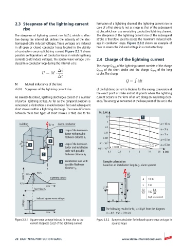
The steepness of lightning current rise Δi/Δt, which is effec- The steepness of the lightning current rise of the subsequent
tive during the interval Δt, defines the intensity of the elec- stroke is therefore used to assess the maximum induced volt-
tromagnetically induced voltages. These voltages are induced age in conductor loops. Figure 2.3.2 shows an example of
in all open or closed conductor loops located in the vicinity how to assess the induced voltage in a conductor loop.
of conductors carrying lightning current. Figure 2.3.1 shows
possible configurations of conductor loops in which lightning
currents could induce voltages. The square wave voltage U in- 2.4 Charge of the lightning current
duced in a conductor loop during the interval αt is:
The charge Q flash of the lightning current consists of the charge
i Q short of the short stroke and the charge Q long of the long
U = M stroke. The charge
t
Q = idt
M Mutual inductance of the loop
Δi/Δt Steepness of the lightning current rise of the lightning current is decisive for the energy conversion at
the exact point of strike and at all points where the lightning
As already described, lightning discharges consist of a number current occurs in the form of an arc along an insulating clear-
of partial lightning strikes. As far as the temporal position is ance. The energy W converted at the base point of the arc is the
concerned, a distinction is made between first and subsequent
short strokes within a lightning discharge. The main difference
between these two types of short strokes is that, due to the M 2 (µH)
10
1
building Î / T1 down conductor a = 10 m
0.1
Loop of the down con- a = 3 m
ductor with possible 0.01 a = 1 m
flashover distance s 1 0.001
s 1 -3 a = 0.1 m
s 3 Loop of the down con- 0.1 · 10 a = 0.3 m
ductor and installation 0.01 · 10 -3 a = 0.01 m
s 2 a = 0.03 m
cable with possible 0.1 0.3 1 3 10 30 s (m)
flashover distance s 2
Installation loop with Sample calculation
possible flashover based on an installation loop (e.g. alarm system)
distance s 3
100 % ∆i
90 %
current lightning current ∆t
Î a 10 m
10 %
time s 3 m
U
front time T 1 a ∆i kA
∆t 150 µs
induced square-wave voltage a s (high requirement)
voltage U
The following results for M 2 ≈ 4.8 µH from the diagram:
time
T 1 U = 4.8 · 150 = 720 kV
Figure 2.3.1 Square-wave voltage induced in loops due to the Figure 2.3.2 Sample calculation for induced square-wave voltages in
current steepness Δi/Δt of the lightning current squared loops
20 LIGHTNING PROTECTION GUIDE www.dehn-international.com