
Page 18 - 35_DS702_E_2014_Lightning_Protection_Guide
P. 18
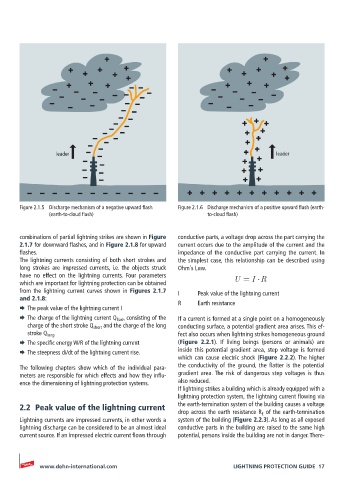
leader                                                          leader


       Figure 2.1.5  Discharge mechanism of a negative upward flash   Figure 2.1.6  Discharge mechanism of a positive upward flash (earth-
               (earth-to-cloud flash)                        to-cloud flash)


       combinations of partial lightning strikes are shown in Figure   conductive parts, a voltage drop across the part carrying the
       2.1.7 for downward flashes, and in Figure 2.1.8 for upward   current occurs due to the amplitude of the current and the
       flashes.                                     impedance of the conductive part carrying the current. In
       The lightning currents consisting of both short strokes and   the simplest case, this relationship can be described using
       long  strokes  are  impressed  currents,  i.e.  the  objects  struck   Ohm´s Law.
       have  no  effect  on  the  lightning  currents.  Four  para meters
       which are important for lightning protection can be obtained   U = I R
       from the lightning current curves shown in Figures 2.1.7   I   Peak value of the lightning current
       and 2.1.8:                                   R     Earth resistance
       ¨  The peak value of the lightning current I
       ¨  The charge of the lightning current Q flash  consisting of the   If a current is formed at a single point on a homogeneously
         charge of the short stroke Q short  and the charge of the long   conducting surface, a potential gradient area arises. This ef-
         stroke Q long                              fect also occurs when lightning strikes homogeneous ground
       ¨  The specific energy W/R of the lightning current  (Figure 2.2.1). If living beings (persons or animals) are
       ¨  The steepness di/dt of the lightning current rise.  inside this potential gradient area, step voltage is formed
                                                    which can cause electric shock (Figure 2.2.2). The higher
       The following chapters show which of the individual para-  the conductivity of the ground, the flatter is the potential
       meters are responsible for which effects and how they influ-  gradient area. The risk of dangerous step voltages is thus
       ence the dimensioning of lightning protection systems.  also reduced.
                                                    If lightning strikes a building which is already equipped with a
                                                    lightning protection system, the lightning current flowing via
       2.2  Peak value of the lightning current     the earth-termination system of the building causes a voltage
                                                    drop across the earth resistance R E  of the earth-termination
       Lightning currents are impressed currents, in other words a   system of the building (Figure 2.2.3). As long as all exposed
       lightning discharge can be considered to be an almost ideal   conductive parts in the building are raised to the same high
       current source. If an impressed electric current flows through   potential, persons inside the building are not in danger. There-


            www.dehn-international.com                              LIGHTNING PROTECTION GUIDE  17