
Page 174 - 35_DS702_E_2014_Lightning_Protection_Guide
P. 174
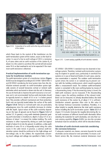
2000
                                                                      copper       galvanised steel
                                                       G = short-circuit current density [A/mm 2 ]  400  (EN 50522,
                                                        1000
                                                        800
                                                        600
                                                        300
                                                                                   Figure D.1)
                                                        200
                                                        150
                                                        100
                                                         80
                                                         60
                                                             316 Ti) determined in
                                                             tests (test report EPM
                                                         20
       Figure 5.9.4  Connection of an earth rod to the ring earth electrode   40  StSt (V4A, AISI/ASTM
                                                             No. 6337 of 16/12/1993)
               of the station
                                                         10
                                                           0.02 0.04 0.08 0.1  0.2  0.40.6 1  2  4 6  10
       which  flows  back  to  the  neutral  of  the  transformer  via  the   t F  = duration of the fault current [s]
       earth-termination system of the station, occurs at the fault lo-
       cation. In case of a line-to-earth voltage of 230 V, a resistance   Figure 5.9.5  Current carrying capability of earth electrode materials
       R E  of some ohms and an earth resistance of the station R B  of
       about 2 Ω, this current is uncritical. The current will not exceed
       some 10 A so that overload is not to be expected if the maxi-
       mum earth resistance is observed.            IEC 61936-1 (EN 61936-1) standard must be observed in low-
                                                    voltage systems. Therefore, isolated earth-termination systems
       Practical implementation of earth-termination sys-  may be required in special cases, particularly in overhead line
       tems for transformer stations                systems or in case of dead-end feeders. In such cases, case-by-
       The earth-termination system of a transformer station (Figure     case examination is required. This outdoor earth-termination
       5.9.3) must be designed according to IEC 61936-1 (EN 61936-1)     system enters the station in an isolated way to prevent con-
       and EN 50522 considering the local system data from the dis-  tact with the building reinforcement, which would negatively
       tribution network operator. An earth-termination system typi-  affect a measurement result. The outdoor earth-termination
       cally consists of several horizontal, vertical or inclined earth   system is connected to the main earthing busbar by means of
       electrodes which are buried or driven into the soil. In Germany,   a disconnecting clamp. If the disconnecting clamp is closed, the
       the use of chemicals to improve the earth resistance is not com-  total earth resistance can be measured. If the disconnecting
       mon and is not recommended. Surface earth electrodes should   clamp is open, the earthing conditions of the relevant instal-
       be typically buried at a depth of 0.5 m to 1 m below ground   lation can be measured. As already described before, the total
       level. This provides sufficient mechanical and frost protection.   earth resistance of the station R B  of about 2 Ω is sufficient.
       Earth rods are typically buried below the surface of the earth   Distribution network operators often refer to this value in
       (Figure 5.9.4). Vertical or inclined earth rods are particularly   the German Technical Connection Conditions. Therefore, it is
       advantageous since the earth resistivity decreases in relation   often helpful to roughly determine the total earth resistance
       with the depth. Typical values of the earth resistivity depend-  before installing the earth-termination system. Table 5.5.1 of
       ing on the type of ground can be found in Figure 5.5.4 of    chapter 5.5 includes formulas for roughly determining the to-
       section 5.5. In general, a ring earth electrode (potential grad-  tal earth resistance of different buried earth electrodes. When
       ing earth electrode) is installed at a depth of about 0.5 m at a   selecting the materials for earth electrodes, not only their cur-
       distance of about 1 m around the station building. The earth   rent carrying capability (Figure 5.9.5), but also the corrosion
       resistance is often improved by driving an earth rod (typical   behaviour must be considered, which will be described below.
       length of about 6 m) into the ground. In addition, a strip earth
       electrode of some 10 m is frequently routed along the cable   Selection of earth electrode materials considering
       routes in the cable trench. In practice, a common earth-ter-  the corrosion behaviour
       mination system should be preferred on the high-voltage and   If adequate materials are chosen, corrosion hazards for earth
       low-voltage side. In this context, the requirements concern-  electrodes can be reduced or even prevented. To ensure a suf-
       ing touch voltage and voltage rise specified in Table 2 of the    ficient  service  life,  the  minimum  material  dimensions  must


            www.dehn-international.com                             LIGHTNING PROTECTION GUIDE  173