
Page 172 - 35_DS702_E_2014_Lightning_Protection_Guide
P. 172
Time St/tZn Copper StSt (V4A) In case of a compensated system, for example, the earth-ter-
2
[s] [A/mm ] [A/mm ] [A/mm ] mination system itself (namely the part in direct contact with
2
2
0.3 129 355 70 earth) is loaded with a considerably lower current, namely only
with the residual earth fault current
0.5 100 275 55
1 70 195 37 I = r I
E RES
3 41 112 21
5 31 87 17 reduced by the factor r (Table 5.9.1). This current does not
exceed some 10 A and can permanently flow without problems
Table 5.9.2 Short-circuit current density G (max. temperature of 200 °C) if common earthing material cross-sections are used. In the
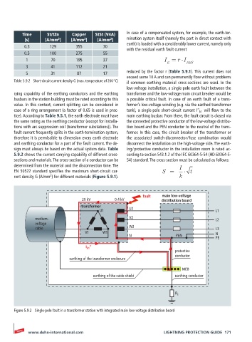
low-voltage installation, a single-pole earth fault between the
rying capability of the earthing conductors and the earthing transformer and the low-voltage main circuit breaker would be
busbars in the station building must be rated according to this a possible critical fault. In case of an earth fault of a trans-
value. In this context, current splitting can be considered in former’s low-voltage winding (e.g. via the earthed transformer
case of a ring arrangement (a factor of 0.65 is used in prac- tank), a single-pole short-circuit current I’’ k1 will flow to the
tice). According to Table 9.5.1, the earth electrode must have main earthing busbar. From there, the fault circuit is closed via
the same rating as the earthing conductor (except for installa- the connected protective conductor of the low-voltage distribu-
tions with arc suppression coil (transformer substations)). The tion board and the PEN conductor to the neutral of the trans-
fault current frequently splits in the earth-termination system, former. In this case, the circuit breaker of the transformer or
therefore it is permissible to dimension every earth electrode the associated switch-disconnector / fuse combination would
and earthing conductor for a part of the fault current. The de- disconnect the installation on the high-voltage side. The earth-
sign must always be based on the actual system data. Table ing / protective conductor in the installation room is rated ac-
5.9.2 shows the current carrying capability of different cross- cording to section 543.1.2 of the IEC 60364-5-54 (HD 60364-5-
sections and materials. The cross-section of a conductor can be 54) standard. The cross-section must be calculated as follows:
determined from the material and the disconnection time. The I
EN 50522 standard specifies the maximum short-circuit cur- S = t
2
rent density G (A/mm ) for different materials (Figure 5.9.1). k
fault main low-voltage
20 kV 0.4 kV distribution board
transformer
U1 U2 L1
medium- V2 L2
voltage
cable W2 L3
V1 W1 N
N PEN
PE
I k1 ‘‘
protective
conductor
earthing of the transformer enclosure
MEB
earthing of the cable shield earthing conductor
R E
Figure 5.9.2 Single-pole fault in a transformer station with integrated main low-voltage distribution board
www.dehn-international.com LIGHTNING PROTECTION GUIDE 171