
Page 170 - 35_DS702_E_2014_Lightning_Protection_Guide
P. 170
systems are defined as an enclosed area where all earth-ter- (typically up to max. 10 % of the uncompensated earth fault
mination systems in this area act like a large common meshed current) stresses the earth-termination system in case of a
earth electrode. A global earth-termination system (industrial fault. The residual current is further reduced by connecting the
plants, residential areas) can typically be assumed if more than local earth-termination system to other earth-termination sys-
ten meshed earth-termination systems are installed in the tems (e.g. by means of the connecting effect of the cable shield
enclosed area. In case of a fault, a wide-ranging quasi equi- of the medium-voltage cables). To this end, a reduction fac-
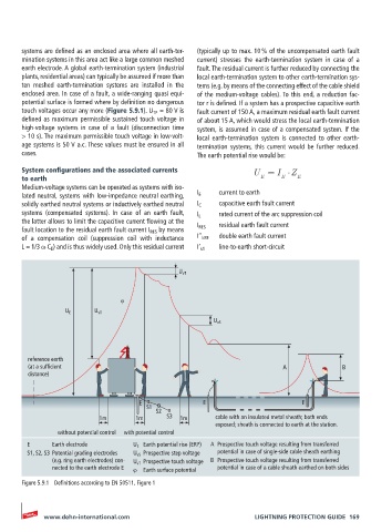
potential surface is formed where by definition no dangerous tor r is defined. If a system has a prospective capacitive earth
touch voltages occur any more (Figure 5.9.1). U TP = 80 V is fault current of 150 A, a maximum residual earth fault current
defined as maximum permissible sustained touch voltage in of about 15 A, which would stress the local earth-termination
high-voltage systems in case of a fault (disconnection time system, is assumed in case of a compensated system. If the
> 10 s). The maximum permissible touch voltage in low-volt- local earth-termination system is connected to other earth-
age systems is 50 V a.c. These values must be ensured in all termination systems, this current would be further reduced.
cases. The earth potential rise would be:
System configurations and the associated currents U = I Z
to earth E E E
Medium-voltage systems can be operated as systems with iso-
lated neutral, systems with low-impedance neutral earthing, I E current to earth
solidly earthed neutral systems or inductively earthed neutral I C capacitive earth fault current
systems (compensated systems). In case of an earth fault, I L rated current of the arc suppression coil
the latter allows to limit the capacitive current flowing at the I RES residual earth fault current
fault location to the residual earth fault current I RES by means
of a compensation coil (suppression coil with inductance I’’ kEE double earth fault current
L = 1/3 ω C E ) and is thus widely used. Only this residual current I’ k1 line-to-earth short-circuit
U vT
ϕ
U E U vT
U vS
reference earth
(at a sufficient A B
distance)
E E E
S1
S2
1m 1m S3 1m cable with an insulated metal sheath; both ends
exposed; sheath is connected to earth at the station.
without potential control with potential control
E Earth electrode U E Earth potential rise (ERP) A Prospective touch voltage resulting from transferred
S1, S2, S3 Potential grading electrodes U vS Prospective step voltage potential in case of single-side cable sheath earthing
(e.g. ring earth electrodes) con- U vT Prospective touch voltage B Prospective touch voltage resulting from transferred
nected to the earth electrode E ϕ Earth surface potential potential in case of a cable sheath earthed on both sides
Figure 5.9.1 Definitions according to EN 50511, Figure 1
www.dehn-international.com LIGHTNING PROTECTION GUIDE 169