
Page 171 - 35_DS702_E_2014_Lightning_Protection_Guide
P. 171
I N nominal current U 0 is the nominal voltage to earth of 230 V and
r reduction factor (e.g. for cable shields) U B is the agreed maximum touch voltage of 50 V
Thus, the following must apply: R B / R E ≤ 0.27. If an accidental
Dimensioning of earth-termination systems with contact resistance of 10 Ω (typical empirical value) is assumed
respect to the earth potential rise at the fault location, R B must be ≤ 2.7 Ω. Therefore, in prac-
When planning earthing measures for a medium-voltage sys- tice a maximum limit of R B = 2 Ω is often used for system
tem, the possible earth potential rise U E must be determined. operation. This total earth resistance of the station earth must
If U E < 2 x U TP , the earth potential rise is correctly rated. If be documented before commissioning and must be tested at
U E < 4 x U TP , compensating measures (e.g. potential control) regular intervals.
must be implemented. In special cases, additional measures
must be taken; the exact procedure is described in Figure 5 of Dimensioning of earth-termination systems with
the EN 50522 standard. By definition, there is no impermissibly respect to the current carrying capability
high voltage rise if the relevant installation is part of a global To dimension the current carrying capability of earthing con-
earth-termination system. TN and TT systems are commonly ductors and earth electrodes, different worst case scenarios
used as low-voltage distribution systems, therefore other sys- must be examined. In medium-voltage systems, a double earth
tem configurations are not considered here. Particularly in TN fault would be the most critical case. A first earth fault (for
systems, a voltage may be transferred into the customer instal- example at a transformer) may cause a second earth fault in
lation in case of a fault. The voltage rise at the PEN conductor another phase (for example in the medium-voltage system,
must not exceed 50 V in TN systems and 250 V in TT systems. faulty cable sealing end). In this case, a double earth fault cur-
In this context, IEC 60364-4-41 (HD 60364-4-41) refers to the rent I’’ kEE , which is defined as follows according to Table 1 of
so-called voltage balance. This is ensured if
the EN 50522 standard, will flow via the earthing conductors
R U (Table 5.9.1):
B B
R (U U ) I '' 0.85 I ''
E 0 B kEE k
where
I’’ k = three-pole initial symmetrical short-circuit current
R B is the total resistance of all operational earth
electrodes In a 20 kV installation with an initial symmetrical short-circuit
R E is the earth contact resistance at a possible fault current I’’ k of 16 kA and a disconnection time of 1 second, the
location double earth fault current would be 13.6 kA. The current car-
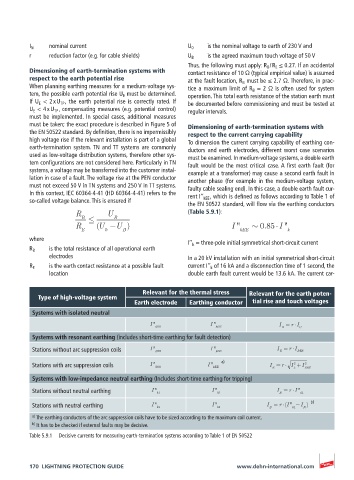
Relevant for the thermal stress Relevant for the earth poten-
Type of high-voltage system
Earth electrode Earthing conductor tial rise and touch voltages
Systems with isolated neutral
I '' I '' I = r I
kEE kEE E C
Systems with resonant earthing (includes short-time earthing for fault detection)
Stations without arc suppression coils I '' kEE I '' kEE I = r I RES
E
2
Stations with arc suppression coils I '' kEE I '' kEE a) I = r I + I 2 RES
L
E
Systems with low-impedance neutral earthing (Includes short-time earthing for tripping)
Stations without neutral earthing I '' k1 I '' k1 I = r I '' k1
E
Stations with neutral earthing I '' k1 I '' k1 I = r (I '' k1 I ) b)
N
E
a) The earthing conductors of the arc suppression coils have to be sized according to the maximum coil current.
b) It has to be checked if external faults may be decisive.
Table 5.9.1 Decisive currents for measuring earth-termination systems according to Table 1 of EN 50522
170 LIGHTNING PROTECTION GUIDE www.dehn-international.com