
Page 173 - 35_DS702_E_2014_Lightning_Protection_Guide
P. 173
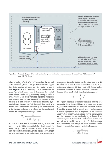
Potential grading earth electrode
                      earthing busbar in the station,                     (closed ring), e.g. StSt (V4A),
                      e.g. St/tZn, 30 x 3.5 mm,                           30 x 3.5 mm, installed around
                      closed ring
                                                                          the station, spaced at intervals
                                                                          between 0.8 m and 1 m, buried
                                                                          at a depth of about 0.5 m
                                                      trans-
                                         MV switchgear
                                      LV distribution board  main earthing  cabinet
                                                      former
                                         installation
                                                       cable
                                        busbar (MEB)
                                                      cabinet
                                        with earth
                                        disconnecting
                                                                           earth rod, e.g. StSt (V4A),
                                        clamp                              If required, additional
                                                       cable               ∅ 20 mm, about 5 m
                                                      cabinet
                       transformer

                   insulated earth                                         Additional earthing conductor,
                   electrode bushing                                       e.g. StSt (V4A), 30 x 3.5 mm
                                                                           installed in the cable trench,
                                                                           in every direction about 30 m


          Figure 5.9.3  Schematic diagram of the earth-termination system at a transformer station (source: Niemand / Kunz; “Erdungsanlagen”,
                  page 109; VDE-Verlag)


          where according to Table A 54.2 of the standard the material   voltage side. According to the transformation ratio n of 50,
          factor k (insulated, thermoplastic) is 143 in case of a copper   the short-circuit current would be transformed to the high-
          line, I is the short-circuit current and t the duration of current   voltage side with about 450 A and trip the HH fuses according
          flow (Figure 5.9.2). It is extremely difficult to calculate the   to the fuse characteristic curve at a nominal current of 31.5 A
          actual flow of fault current since it depends on the nominal   in about 25 ms (on all poles). According to the equation
          power of the transformer S N  , the driving voltage, the short-   I
          circuit voltage u k  and the relevant loop impedance (which can   S  =    t
          only be determined by measurements). Fast analysis is only        k
          possible to a limited extent by considering the initial sym-  the copper protective conductors / protective bonding con-
          metrical short-circuit current I’’ k  (~three-pole short-circuit as a   ductors in the station would have a minimum cross-section
                                                                2
                                                                                                2
          defined state) which can be calculated by the nominal power   S min  = 25 mm . In practice, this value is rounded up to 50 mm .
          of the transformer, the nominal voltage and the short-circuit   It must be observed that in case of larger transformers and
          voltage according to the following equation:  consequently higher currents in conjunction with the relevant
                                S                      disconnection times the cross-sections for the protective and
                    I '' =       N                     earthing conductor can be considerably higher. The earth-ter-
                       k
                           ( 3 U    u )                mination system itself (namely the part in direct contact with
                                 N   k
                                                       earth) is not stressed in case of this fault. On the low-voltage
          In  case  of  a  630  kVA  transformer  with  u k  = 4 % and     side, currents only flow through the earth-termination system
          U N  = 400 V, the initial symmetrical short-circuit current I’’ k    in case of an earth fault outside the station. The current
          would be e.g. 22.7 kA. In our example with a 20 kV installa-        U
          tion, the transformer would have to be protected by means of   I =
                                                                     E
          HH fuses with a nominal current from 31.5 to 50 A on the high-  (R + R )
                                                                                  B
                                                                            E

          172  LIGHTNING PROTECTION GUIDE                            www.dehn-international.com