
Page 23 - 35_DS702_E_2014_Lightning_Protection_Guide
P. 23
2
Cross-section [mm ] 4 10 16 25 50 100
specific energy
W/R 2.5 – 564 146 52 12 3
Aluminium
5.6 – – 454 132 28 7
W/R [MJ/Ω]
10 – – – 283 52 12
2.5 – – 1120 211 37 9
Iron
5.6 – – – 913 96 20
force on W/R [MJ/Ω]
parallel 10 – – – – 211 37
conductors Material Copper 2.5 – 169 56 22 5 1
W/R [MJ/Ω] 5.6 – 542 143 51 12 3
specific 10 – – 309 98 22 5
energy Stainless 2.5 – – – 940 190 45
steel 5.6 – – – – 460 100
lightning
temperature rise W/R [MJ/Ω]
current 10 – – – – 940 190
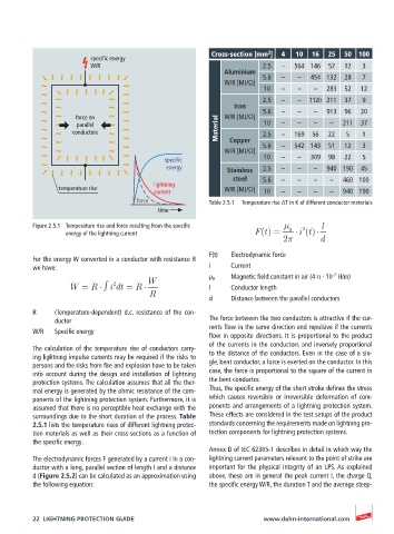
force Table 2.5.1 Temperature rise ΔT in K of different conductor materials
time
Figure 2.5.1 Temperature rise and force resulting from the specific µ 0 2 l
energy of the lightning current F(t) = i (t)
2 d
F(t) Electrodynamic force
For the energy W converted in a conductor with resistance R
we have: i Current
-7
W µ 0 Magnetic field constant in air (4 π · 10 H/m)
2
W = R i dt = R l Conductor length
R
d Distance between the parallel conductors
R (Temperature-dependent) d.c. resistance of the con-
ductor The force between the two conductors is attractive if the cur-
rents flow in the same direction and repulsive if the currents
W/R Specific energy
flow in opposite directions. It is proportional to the product
of the currents in the conductors and inversely proportional
The calculation of the temperature rise of conductors carry-
ing lightning impulse currents may be required if the risks to to the distance of the conductors. Even in the case of a sin-
persons and the risks from fire and explosion have to be taken gle, bent conductor, a force is exerted on the conductor. In this
into account during the design and installation of lightning case, the force is proportional to the square of the current in
protection systems. The calculation assumes that all the ther- the bent conductor.
mal energy is generated by the ohmic resistance of the com- Thus, the specific energy of the short stroke defines the stress
ponents of the lightning protection system. Furthermore, it is which causes reversible or irreversible deformation of com-
assumed that there is no perceptible heat exchange with the ponents and arrangements of a lightning protection system.
surroundings due to the short duration of the process. Table These effects are considered in the test setups of the product
2.5.1 lists the temperature rises of different lightning protec- standards concerning the requirements made on lightning pro-
tion materials as well as their cross-sections as a function of tection components for lightning protection systems.
the specific energy.
Annex D of IEC 62305-1 describes in detail in which way the
The electrodynamic forces F generated by a current i in a con- lightning current parameters relevant to the point of strike are
ductor with a long, parallel section of length I and a distance important for the physical integrity of an LPS. As explained
d (Figure 2.5.2) can be calculated as an approximation using above, these are in general the peak current I, the charge Q,
the following equation: the specific energy W/R, the duration T and the average steep-
22 LIGHTNING PROTECTION GUIDE www.dehn-international.com