
Page 192 - 35_DS702_E_2014_Lightning_Protection_Guide
P. 192
7.3 Calculation of the magnetic shield for the electrical installation to be protected, the calculations
attenuation of building / room must be performed with the maximum value of the current of
the first positive stroke (i f/max ) and of the first negative stroke
shields (i fn/max ) and with the maximum value of the current of the sub-
Lightning currents and the associated electromagnetic field sequent strokes (i s/max ) according to the lightning protection
represent the primary source of interference for devices and level (LPL) given in Table 3 of the IEC 62305-1 (EN 62305-1)
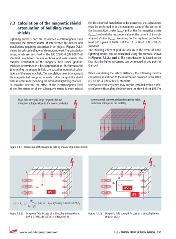
installations requiring protection in an object. Figure 7.3.1 standard.
shows the principle of how grid structures work. The calculation The shielding effect of grid-like shields in the event of direct
bases, which are described in the IEC 62305-4 (EN 62305-4) lightning strikes can be calculated using the formula shown
standard, are based on assumptions and assessments. The in Figures 7.3.2a and b. This consideration is based on the
complex distribution of the magnetic field inside grid-like fact that the lightning current can be injected at any point of
shields is determined in a first approximation. The formulas for the roof.
determining the magnetic field are based on numerical calcu-
lations of the magnetic field. The calculation takes into account When calculating the safety distances, the following must be
the magnetic field coupling of each rod in the grid-like shield considered in addition to the information provided in the latest
with all other rods including the simulated lightning channel. IEC 62305-4 (EN 62305-4) standard:
To consider whether the effect of the electromagnetic field Internal electronic systems may only be installed within a safe-
of the first stroke or of the subsequent stroke is more critical ty volume with a safety distance from the shield of the LPZ. The
High field strength, large magnetic fields / Lower partial currents, reduced magnetic fields /
induction voltages close to the down conductor induction voltages in the building
Figure 7.3.1 Reduction of the magnetic field by means of grid-like shields
i o
w w
i
d r
d r
d w
H 2
d w
W
H k i O m [A/m] i o = lightning current in LPZ 0 A
h
1
d d
W r
Figure 7.3.2a Magnetic field in case of a direct lightning strike in Figure 7.3.2b Magnetic field strength in case of a direct lightning
LPZ 1 (LEMP), IEC 62305-4 (EN 62305-4) strike in LPZ 2
www.dehn-international.com LIGHTNING PROTECTION GUIDE 191