
Page 197 - 35_DS702_E_2014_Lightning_Protection_Guide
P. 197
2
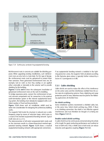
at least 50 mm (St/tZn)
earthing bus conductor
connection to the
earthing bus conductor
reinforcement
Figure 7.3.9 Earthing bus conductor / ring equipotential bonding
Reinforcement mats in concrete are suitable for shielding pur- If an equipotential bonding network is installed in the light-
poses. When upgrading existing installations, such reinforce- ning protection zones, the magnetic field calculated according
ment mats are also laid at a later date. For this type of design, to the formulas given above is typically further reduced by a
the reinforcement mats must be galvanised to protect them factor of 2 (corresponds to 6 dB).
from corrosion. These galvanised reinforcement mats are, for
example, laid on roofs so that they overlap or are applied
either externally or internally to the exterior wall to provide 7.3.1 Cable shielding
shielding for the building.
Figures 7.3.7a and b show the subsequent installation of Cable shields are used to reduce the effect of the interference
galvanised reinforcement mats on the roof of a building. on the active cores and the interference emitted from the ac-
To bridge expansion joints, connect the reinforcement of pre- tive cores to neighbouring systems. From a lightning and surge
cast concrete components and for connection to the external protection point of view, attention must be paid to the follow-
earth-termination system or the internal equipotential bond- ing applications of shielded lines:
ing system, the building must already be equipped with a suf-
ficient number of fixed earthing terminals. No shield earthing
Figure 7.3.8 shows such an installation, which must be Some installation systems recommend a shielded cable, but,
taken into consideration for designing the preliminary building at the same time, forbid shield earthing (e.g. KNX). If there
works. is no shielding connection, the shield is not effective against
The magnetic field inside the structure is reduced over a wide interferences and must therefore be thought of as being not
frequency range by means of reduction loops, which arise as there (Figure 7.3.1.1).
a result of the meshed equipotential bonding network. Typical
mesh sizes are a ≤ 5 m. Double-ended shield earthing
The interconnection of all metal components both inside and A cable shield must be continuously connected along the whole
on the structures results in a three-dimensional meshed equi- of its length for good conducting performance and earthed at
potential bonding network. Figure 7.3.9 shows a meshed least at both ends. Only a shield used at both ends can reduce
equipotential bonding network with appropriate connections. inductive and capacitive coupling (Figure 7.3.1.2).
196 LIGHTNING PROTECTION GUIDE www.dehn-international.com