
Page 195 - 35_DS702_E_2014_Lightning_Protection_Guide
P. 195
without shield:
field of the field of the
lightning H i o [A/m] lightning H i o
channel 0 2 S channel 0 2 S
a a
with shield:
H 0
H 0 H 1 H
H 0
s a s a 1 10 SF /20
1
Figure 7.3.4 Magnetic field in case of a nearby lightning strike Figure 7.3.5 Magnetic field in case of a nearby lightning strike
(LEMP), IEC 62305-4 (EN 62305-4) (LEMP), IEC 62305-4 (EN 62305-4)
¨ Caused by the subsequent strokes:
H a 5 2
H = 0/s/max in A/m 1
1/s/max SF/20
10
These magnetic field values are only valid for a safety volume 3 9
V s inside the grid-like shield with a safety distance d s/2 from the a b
shield (Figure 7.3.3). 6
4
d = w SF/20 for SF 10 in m
s/2 m 7
d = w for SF < 10 in m
s/2 m 9
8
where
12
SF is the shielding factor determined using the equations
in Table 7.3.1 in dB;
11
w m is the mesh size of the grid-like shield in m. 10
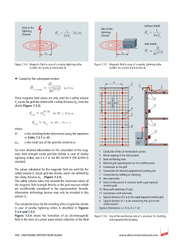
For more detailed information on the calculation of the mag- 1 Conductor of the air-termination system
netic field strength inside grid-like shields in case of nearby 2 Metal capping of the roof parapet
lightning strikes, see A.4.3 of the IEC 62305-4 (EN 62305-4) 3 Steel reinforcing rods
standard. 4 Meshed grid superimposed on the reinforcement
5 Connection to the grid
The values calculated for the magnetic field are valid for the 6 Connection for internal equipotential bonding bar
safety volume V s inside grid-like shields, which are defined by 7 Connection by welding or clamping
the safety distance d s/… (Figure 7.3.3). 8 Any connection
This safety volume takes into account the maximum values of 9 Steel reinforcement in concrete (with superimposed
the magnetic field strength directly at the grid structure which meshed grid)
are insufficiently considered in the approximation formula. 10 Ring earth electrode (if any)
Information technology devices may only be installed in this 11 Foundation earth electrode
volume V s . a Typical distance of 5 m in the superimposed meshed grid
b Typical distance of 1 m for connecting this grid to the
The calculation basis for the shielding effect of grid-like shields reinforcement
in case of nearby lightning strikes is described in Figures (typical dimensions: a ≤ 5 m, b ≤ 1 m)
7.3.4 and 7.3.5.
Figure 7.3.4 shows the formation of an electromagnetic Figure 7.3.6 Use of the reinforcing rods of a structure for shielding
field in the form of a plane wave whose reduction of the field and equipotential bonding
194 LIGHTNING PROTECTION GUIDE www.dehn-international.com