
Page 196 - 35_DS702_E_2014_Lightning_Protection_Guide
P. 196
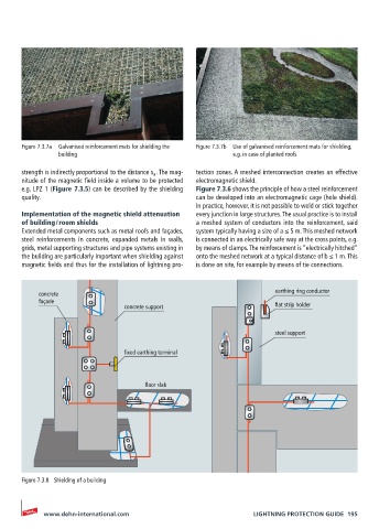
Figure 7.3.7a  Galvanised reinforcement mats for shielding the   Figure 7.3.7b  Use of galvanised reinforcement mats for shielding,
                building                                      e.g. in case of planted roofs
       strength is indirectly proportional to the distance s a  . The mag-  tection zones. A meshed interconnection creates an effective
       nitude of the magnetic field inside a volume to be protected   electromagnetic shield.
       e.g. LPZ 1 (Figure 7.3.5) can be described by the shielding   Figure 7.3.6 shows the principle of how a steel reinforcement
       quality.                                     can be developed into an electromagnetic cage (hole shield).
                                                    In practice, however, it is not possible to weld or stick together
       Implementation of the magnetic shield attenuation   every junction in large structures. The usual practice is to install
       of building / room shields                   a meshed system of conductors into the reinforcement, said
       Extended metal components such as metal roofs and façades,   system typically having a size of a ≤ 5 m. This meshed network
       steel reinforcements in concrete, expanded metals in walls,   is connected in an electrically safe way at the cross points, e.g.
       grids, metal supporting structures and pipe systems existing in   by means of clamps. The reinforcement is “electrically hitched”
       the building are particularly important when shielding against   onto the meshed network at a typical distance of b ≤ 1 m. This
       magnetic fields and thus for the installation of lightning pro-  is done on site, for example by means of tie connections.


           concrete                                                      earthing ring conductor
           façade
                                  concrete support                       flat strip holder


                                                                         steel support

                                  fixed earthing terminal


                                       floor slab


       Figure 7.3.8  Shielding of a building


            www.dehn-international.com                             LIGHTNING PROTECTION GUIDE  195