
Page 206 - 35_DS702_E_2014_Lightning_Protection_Guide
P. 206
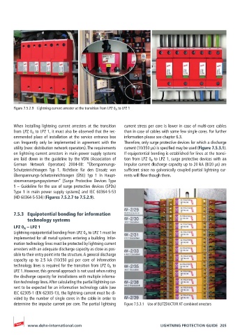
Figure 7.5.2.9  Lightning current arrester at the transition from LPZ 0 A  to LPZ 1


       When installing lightning current arresters at the transition   current stress per core is lower in case of multi-core cables
       from LPZ 0 A  to LPZ 1, it must also be observed that the rec-  than in case of cables with some few single cores. For further
       ommended place of installation at the service entrance box   information please see chapter 6.3.
       can frequently only be implemented in agreement with the   Therefore, only surge protective devices for which a discharge
       utility (new: distribution network operators). The requirements   current (10/350 µs) is specified may be used (Figure 7.5.3.1).
       on lightning current arresters in main power supply systems   If equipotential bonding is established for lines at the transi-
       are  laid  down  in  the  guideline  by  the VDN  (Association  of   tion from LPZ 0 B  to LPZ 1, surge protective devices with an
       German Network Operators) 2004-08:  “Überspannungs-  impulse current discharge capacity up to 20 kA (8/20 µs) are
       Schutzeinrichtungen  Typ 1. Richtlinie für den Einsatz von   sufficient since no galvanically coupled partial lightning cur-
       Überspannungs-Schutzeinrichtungen (ÜSE)  Typ 1 in Haupt-  rents will flow though them.
       stromversorgungssystemen“ [Surge Protective Devices  Type
       1 – Guideline for the use of surge protective devices (SPDs)
       Type 1 in main power supply systems] and IEC 60364-5-53
       (HD 60364-5-534) (Figures 7.5.2.7 to 7.5.2.9).


       7.5.3  Equipotential bonding for information
            technology systems
       LPZ 0 A  – LPZ 1
       Lightning equipotential bonding from LPZ 0 A  to LPZ 1 must be
       implemented for all metal systems entering a building. Infor-
       mation technology lines must be protected by lightning current
       arresters with an adequate discharge capacity as close as pos-
       sible to their entry point into the structure. A general discharge
       capacity  up  to  2.5  kA  (10/350  μs)  per  core  of  information
       technology lines is required for the transition from LPZ 0 A  to
       LPZ 1. However, this general approach is not used when rating
       the discharge capacity for installations with multiple informa-
       tion technology lines. After calculating the partial lightning cur-
       rent to be expected for an information technology cable (see
       IEC 62305-1 (EN 62305-1)), the lightning current must be di-
       vided by the number of single cores in the cable in order to
       determine the impulse current per core. The partial lightning   Figure 7.5.3.1  Use of BLITZDUCTOR XT combined arresters


            www.dehn-international.com                             LIGHTNING PROTECTION GUIDE  205