
Page 345 - 35_DS702_E_2014_Lightning_Protection_Guide
P. 345
External lightning protection measures
These include:
¨ Air-termination and down-conductor systems in the rotor
blades
¨ Air-termination systems for protecting nacelle superstruc-
tures, the nacelle and the hub
¨ Using the tower as air-termination system and down con-
ductor
¨ Earth-termination system consisting of a foundation earth
electrode and a ring earth electrode
The function of an external lightning protection system (LPS)
is to intercept direct lightning strikes including lightning
strikes to the tower of a wind turbine and to discharge the
lightning current from the point of strike to the ground. An
external lightning protection system is also used to distribute
the lightning current in the ground without causing thermal or
mechanical damage or dangerous sparking which may lead to
fire or explosion and endanger persons.
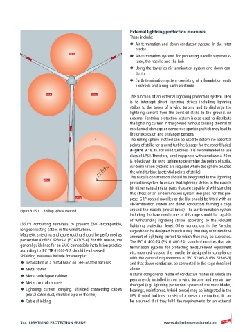
The rolling sphere method can be used to determine potential
points of strike for a wind turbine (except for the rotor blades)
(Figure 9.16.1). For wind turbines, it is recommended to use
class of LPS I. Therefore, a rolling sphere with a radius r = 20 m
is rolled over the wind turbine to determine the points of strike.
r = 20 m Air-termination systems are required where the sphere touches
the wind turbine (potential points of strike).
The nacelle construction should be integrated in the lightning
protection system to ensure that lightning strikes to the nacelle
hit either natural metal parts that are capable of withstanding
this stress or an air-termination system designed for this pur-
pose. GRP-coated nacelles or the like should be fitted with an
air-termination system and down conductors forming a cage
Figure 9.16.1 Rolling sphere method around the nacelle (metal braid). The air-termination system
including the bare conductors in this cage should be capable
of withstanding lightning strikes according to the relevant
(360 °) contacting terminals to prevent EMC-incompatible, lightning protection level. Other conductors in the Faraday
long connecting cables in the wind turbine. cage should be designed in such a way that they withstand the
Magnetic shielding and cable routing should be performed as amount of lightning current to which they may be subjected.
per section 4 of IEC 62305-4 (EC 62305-4). For this reason, the The IEC 61400-24 (EN 61400-24) standard requires that air-
general guidelines for an EMC-compatible installation practice termination systems for protecting measurement equipment
according to IEC / TR 61000-5-2 should be observed. etc. mounted outside the nacelle be designed in compliance
Shielding measures include for example: with the general requirements of lEC 62305-3 (EN 62305-3)
¨ Installation of a metal braid on GRP-coated nacelles and that down conductors be connected to the cage described
¨ Metal tower above.
¨ Metal switchgear cabinet Natural components made of conductive materials which are
¨ Metal control cabinets permanently installed in / on a wind turbine and remain un-
changed (e.g. lightning protection system of the rotor blades,
¨ Lightning current carrying, shielded connecting cables bearings, mainframes, hybrid tower) may be integrated in the
(metal cable duct, shielded pipe or the like) LPS. If wind turbines consist of a metal construction, it can
¨ Cable shielding be assumed that they fulfil the requirements for an external
344 LIGHTNING PROTECTION GUIDE www.dehn-international.com