
Page 346 - 35_DS702_E_2014_Lightning_Protection_Guide
P. 346
lightning protection system of class of LPS I according to IEC 61400-24 (EN 61400-24) standard refers to IEC / TS 60479-1
IEC 62305 (EN 62305). and IEC 60479-4.
This requires that the lightning strike be safely intercepted by
the lightning protection system of the rotor blades so that it Arrangement of earth electrodes
can be discharged to the earth-termination system via the The IEC 62305-3 (EN 62305-3) standard describes two basic
natural components such as bearings, mainframes, the tower types of earth electrode arrangements for wind turbines:
and / or bypass systems (e.g. open spark gaps, carbon brushes).
Type A: According to the informative Annex I of IEC 61400-24
Air-termination system / down conductor (EN 61400-24), this arrangement must not be used for wind
As can be seen in Figure 9.16.1, the turbines, but for adjoining buildings of wind turbines (for ex-
¨ Rotor blades, ample, buildings containing measurement equipment or office
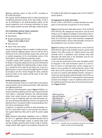
¨ Nacelle including superstructures sheds of a wind farm). Type A earth electrode arrangements
(Figure 9.16.2, Table 9.16.1), consist of horizontal or vertical earth electrodes connected to
¨ Rotor hub and the building by at least two down conductors.
¨ Tower of the wind turbine Type B: According to the informative Annex I of IEC 61400-24
may be hit by lightning. If they are capable of safely intercept- (EN 61400-24), type B earth electrodes must be used for wind
ing the maximum lightning impulse current of 200 kA and to turbines. They either consist of a buried external ring earth
discharge it to the earth-termination system, they can be used electrode and / or a foundation earth electrode. Ring earth
as natural components of the air-termination system of the electrodes and metal parts in the foundation must be con-
wind turbine’s external lightning protection system. nected to the tower construction.
A metallic receptor, which represents a defined point of strike In any case, the reinforcement of the tower foundation should
for flashes, is frequently attached to the tip of the GRP blade to be integrated in the earth-termination system of a wind tur-
protect the rotor blades from lightning strikes. A down conduc- bine. To ensure an earth-termination system ranging over as
tor is routed from the receptor to the blade root. In case of a large an area as possible, the earth-termination system of the
lightning strike, it can be assumed that lightning hits the blade tower base and the operations building should be connected
tip (receptor) and then travels through the down conductor by means of a meshed earth electrode network. Corrosion-re-
inside the blade via the nacelle and the tower to the earth-
termination system. sistant ring earth electrodes (made of stainless steel (V4A), e.g.
material No. AISI / ASTM 316 Ti) with potential control prevent
Earth-termination system excessive step voltages in case of a lightning strike and must
The earth-termination system of a wind turbine must perform be installed around the tower base to ensure personal protec-
several functions such as personal protection, EMC protection tion (Figure 9.16.3).
and lightning protection.
An effective earth-termination system (Figure 9.16.3) is es-
sential to distribute lightning currents and to prevent that the
wind turbine is destroyed. Moreover, the earth-termination GRP/Al supporting
system must protect persons and animals against electric tube with integrated
shock. In case of a lightning strike, the earth-termination sys- high-voltage-insu-
tem must discharge high lightning currents to the ground and lated conductor
distribute them in the ground without causing dangerous ther- (HVI Conductor)
mal and / or electrodynamic effects.
In general, it is important to install an earth-termination sys-
tem for a wind turbine which is used to protect the wind tur-
bine against lightning strikes and to earth the power supply
system.
Note: Electrical high-voltage regulations such as CENELEC
HO 637 S1 or applicable national standards describe how to
design an earth-termination system to prevent high touch
and step voltages caused by short-circuits in high or medium- Figure 9.16.2 Example of an air-termination system for the weather
voltage systems. With regard to the protection of persons, the station and the aircraft warning light
www.dehn-international.com LIGHTNING PROTECTION GUIDE 345