
Page 366 - 35_DS702_E_2014_Lightning_Protection_Guide
P. 366
excessive shading. Diffuse shadows cast by, for example
overhead lines, do not significantly affect the PV system and
the yield. However, in case of core shadows, a dark clearly distance l
outlined shadow is cast on the surface behind an object, Ø air-ter- in m
changing the current flowing through the PV modules. For mination
this reason, solar cells and the associated bypass diodes must rod in mm
not be influenced by core shadows. This can be achieved by
maintaining a sufficient distance. For example, if an air-ter- core shadow
mination rod with a diameter of 10 mm shades a module,
the core shadow is steadily reduced as the distance from the
module increases. After 1.08 m only a diffuse shadow is cast
on the module (Figure 9.18.4). Annex A of Supplement 5 Ø air-termination rod x factor = distance l
of the German DIN EN 62305-3 standard provides more de- 10 mm 108 1.08 m
tailed information on the calculation of core shadows.
16 mm 108 1.76 m
Special surge protective devices for the d.c. side of Figure 9.18.4 Distance between the module and the air-termination
photovoltaic systems rod required to prevent core shadows
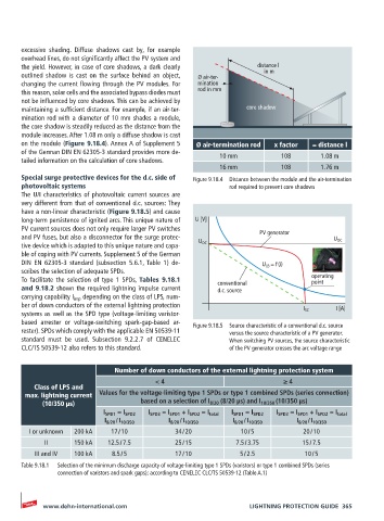
The U/I characteristics of photovoltaic current sources are
very different from that of conventional d.c. sources: They
have a non-linear characteristic (Figure 9.18.5) and cause
long-term persistence of ignited arcs. This unique nature of U [V]
PV current sources does not only require larger PV switches
and PV fuses, but also a disconnector for the surge protec- PV generator U OC
tive device which is adapted to this unique nature and capa- U OC
ble of coping with PV currents. Supplement 5 of the German
DIN EN 62305-3 standard (subsection 5.6.1, Table 1) de- U LB = f (i)
scribes the selection of adequate SPDs.
To facilitate the selection of type 1 SPDs, Tables 9.18.1 conventional operating
point
and 9.18.2 shown the required lightning impulse current d.c. source
carrying capability I imp depending on the class of LPS, num-
ber of down conductors of the external lightning protection I [A]
systems as well as the SPD type (voltage-limiting varistor- I SC
based arrester or voltage-switching spark-gap-based ar- Figure 9.18.5 Source characteristic of a conventional d.c. source
rester). SPDs which comply with the applicable EN 50539-11 versus the source characteristic of a PV generator.
standard must be used. Subsection 9.2.2.7 of CENELEC When switching PV sources, the source characteristic
CLC/TS 50539-12 also refers to this standard. of the PV generator crosses the arc voltage range
Number of down conductors of the external lightning protection system
< 4 ≥ 4
Class of LPS and
max. lightning current Values for the voltage-limiting type 1 SPDs or type 1 combined SPDs (series connection)
(10/350 µs) based on a selection of I 8/20 (8/20 µs) and I 10/350 (10/350 µs)
I SPD1 = I SPD2 I SPD3 = I SPD1 + I SPD2 = I total I SPD1 = I SPD2 I SPD3 = I SPD1 + I SPD2 = I total
I 8/20 / I 10/350 I 8/20 / I 10/350 I 8/20 / I 10/350 I 8/20 / I 10/350
I or unknown 200 kA 17 / 10 34 / 20 10 / 5 20 / 10
II 150 kA 12.5 / 7.5 25 / 15 7.5 / 3.75 15 / 7.5
III and IV 100 kA 8.5 / 5 17 / 10 5 / 2.5 10 / 5
Table 9.18.1 Selection of the minimum discharge capacity of voltage-limiting type 1 SPDs (varistors) or type 1 combined SPDs (series
connection of varistors and spark gaps); according to CENELEC CLC/TS 50539-12 (Table A.1)
www.dehn-international.com LIGHTNING PROTECTION GUIDE 365