
Page 371 - 35_DS702_E_2014_Lightning_Protection_Guide
P. 371
that an additional type 2 d.c. arrester be installed on the
module side if the distance between the inverter input and
the PV generator exceeds 10 m.
The a.c. outputs of the inverters are sufficiently protected if the
distance between the PV inverters and the place of installation
of the type 2 arrester at the grid connection point (low-voltage
infeed) is less than 10 m. In case of greater cable lengths,
an additional type 2 surge protective device, for example
DEHNguard M … 275, must be installed upstream of the a.c.
input of the inverter as per CENELEC CLC/TS 50539-12.
Moreover, a type 2 DEHNguard M … CI 275 (FM) surge pro-
tective device must be installed upstream of the meter of
the low-voltage infeed. CI (Circuit Interruption) stands for a
coordinated fuse integrated in the protective path of the ar-
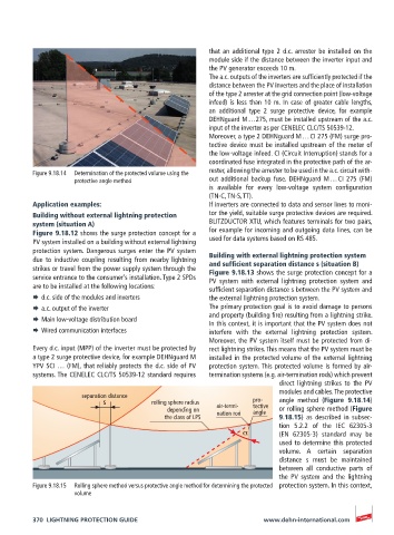
Figure 9.18.14 Determination of the protected volume using the rester, allowing the arrester to be used in the a.c. circuit with-
protective angle method out additional backup fuse. DEHNguard M … CI 275 (FM)
is available for every low-voltage system configuration
(TN-C, TN-S, TT).
Application examples: If inverters are connected to data and sensor lines to moni-
Building without external lightning protection tor the yield, suitable surge protective devices are required.
system (situation A) BLITZDUCTOR XTU, which features terminals for two pairs,
Figure 9.18.12 shows the surge protection concept for a for example for incoming and outgoing data lines, can be
PV system installed on a building without external lightning used for data systems based on RS 485.
protection system. Dangerous surges enter the PV system
due to inductive coupling resulting from nearby lightning Building with external lightning protection system
and sufficient separation distance s (situation B)
strikes or travel from the power supply system through the Figure 9.18.13 shows the surge protection concept for a
service entrance to the consumer’s installation. Type 2 SPDs PV system with external lightning protection system and
are to be installed at the following locations: sufficient separation distance s between the PV system and
¨ d.c. side of the modules and inverters the external lightning protection system.
¨ a.c. output of the inverter The primary protection goal is to avoid damage to persons
and property (building fire) resulting from a lightning strike.
¨ Main low-voltage distribution board
In this context, it is important that the PV system does not
¨ Wired communication interfaces interfere with the external lightning protection system.
Moreover, the PV system itself must be protected from di-
Every d.c. input (MPP) of the inverter must be protected by rect lightning strikes. This means that the PV system must be
a type 2 surge protective device, for example DEHNguard M installed in the protected volume of the external lightning
YPV SCI … (FM), that reliably protects the d.c. side of PV protection system. This protected volume is formed by air-
systems. The CENELEC CLC/TS 50539-12 standard requires termination systems (e.g. air-termination rods) which prevent
direct lightning strikes to the PV
modules and cables. The protective
separation distance
s rolling sphere radius pro- angle method (Figure 9.18.14)
depending on air-termi- tective or rolling sphere method (Figure
angle
nation rod
the class of LPS 9.18.15) as described in subsec-
tion 5.2.2 of the IEC 62305-3
(EN 62305-3) standard may be
used to determine this protected
volume. A certain separation
distance s must be maintained
between all conductive parts of
the PV system and the lightning
Figure 9.18.15 Rolling sphere method versus protective angle method for determining the protected protection system. In this context,
volume
370 LIGHTNING PROTECTION GUIDE www.dehn-international.com