
Page 380 - 35_DS702_E_2014_Lightning_Protection_Guide
P. 380
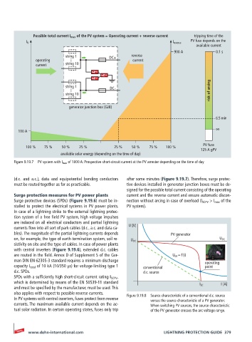
Possible total current I max  of the PV system = Operating current + reverse current  tripping time of the

                                                                              PV fuse depends on the
            I N                                                        I reverse
                                                                                available current
                                                                        900 A           0.1 s
                            string 1         DC+      reverse
               operating      ...                      current
               current      string 10


                            string 1          DC-
                              ...                                                     risk of arcing
                            string 10

                             generator junction box (GJB)

                                                                                        6.5 min

                                                                                        ∞
        100 A

                                                                                   PV fuse
           100 %   75 %   50 %   25 %          25 %   50 %   75 %   100 %
                                                                                  125 A gPV
                          available solar energy (depending on the time of day)
       Figure 9.19.7  PV system with I max  of 1000 A: Prospective short-circuit current at the PV arrester depending on the time of day


       (d.c. and a.c.), data and equipotential bonding conductors   after some minutes (Figure 9.19.7). Therefore, surge protec-
       must be routed together as far as practicable.  tive devices installed in generator junction boxes must be de-
                                                    signed for the possible total current consisting of the operating
       Surge protection measures for PV power plants  current and the reverse current and ensure automatic discon-
       Surge protective devices (SPDs) (Figure 9.19.6) must be in-  nection without arcing in case of overload (I SCPV  > I max  of the
       stalled to protect the electrical systems in PV power plants.   PV system).
       In case of a lightning strike to the external lightning protec-
       tion system of a free field PV system, high voltage impulses
       are induced on all electrical conductors and partial lightning
       currents flow into all sort of park cables (d.c., a.c. and data ca-  U [V]
       bles). The magnitude of the partial lightning currents depends   PV generator
       on, for example, the type of earth-termination system, soil re-  U OC              U OC
       sistivity on site and the type of cables. In case of power plants
       with central inverters (Figure 9.19.6), extended d.c. cables
       are routed in the field. Annex D of Supplement 5 of the Ger-    U LB  = f (i)
       man DIN EN 62305-3 standard requires a minimum discharge                     operating
       capacity I total  of 10 kA (10/350 µs) for voltage-limiting type 1   conventional   point
       d.c. SPDs.                                          d.c. source
       SPDs with a sufficiently high short-circuit current rating I SCPV  ,
       which is determined by means of the EN 50539-11 standard                           I [A]
       and must be specified by the manufacturer, must be used. This              I SC
       also applies with respect to possible reverse currents.
       In PV systems with central inverters, fuses protect from reverse   Figure 9.19.8  Source characteristic of a conventional d.c. source
                                                              versus the source characteristic of a PV generator.
       currents. The maximum available current depends on the ac-  When switching PV sources, the source characteristic
       tual solar radiation. In certain operating states, fuses only trip   of the PV generator crosses the arc voltage range.


            www.dehn-international.com                             LIGHTNING PROTECTION GUIDE  379