
Page 379 - 35_DS702_E_2014_Lightning_Protection_Guide
P. 379
air-termi-
nation rod
data line
IT system central inverter
DNO kWh
earth-termination system
d.c.
Lightning equipotential bonding
foundation Lightning current / combined arrester
earth electrode MEB (main earthing busbar)
Local equipotential bonding
Surge arrester
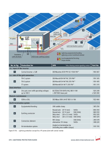
No. in Fig. Protection for SPD * FM = Floating remote signalling contact Part No.
d.c. input of the inverter
Central inverter + GJB DEHNcombo DCB YPV SCI 1500 FM * 900 067
a.c. side of the grid connection
TN-C system DEHNventil DV M TNC 255 FM * 951 305
TN-S system DEHNventil DV M TNS 255 FM * 951 405
TT system DEHNventil DV M TT 255 FM * 951 315
Data interface
One pair, even with operating voltages BLITZDUCTOR BXTU ML2 BD 0-180 920 249
up to 180 V + BXT BAS base part + 920 300
Remote maintenance
ISDN or DSL DEHNbox DBX U4 KT BD S 0-180 922 400
Earth-termination system
Equipotential bonding UNI saddle clamp 365 250
Round wire (Ø 10 mm) St/tZn 800 310
Round wire (Ø 10 mm) StSt (V4A) 860 010
Earthing conductor
Strip steel (30 x 3.5 mm) St/tZn 852 335
Strip steel (30 x 3.5 mm) StSt (V4A) 860 325
MV clamp StSt (V4A) 390 079
Connection element
alternative: SV clamp St/tZn 308 220
Angled air-termination tip
Air-termination system 101 110
(including two saddle clamps)
Figure 9.19.6 Lightning protection concept for a PV power plant with central inverter
378 LIGHTNING PROTECTION GUIDE www.dehn-international.com