
Page 377 - 35_DS702_E_2014_Lightning_Protection_Guide
P. 377
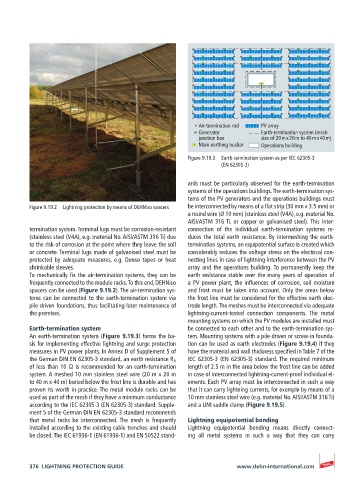
Air-termination rod  PV array
                                                          Generator         Earth-termination system (mesh
                                                          junction box      size of 20 m x 20 m to 40 m x 40 m)
                                                          Main earthing busbar  Operations building
                                                       Figure 9.19.3  Earth-termination system as per IEC 62305-3
                                                                 (EN 62305-3)

                                                       ards must be particularly observed for the earth-termination
                                                       systems of the operations buildings. The earth-termination sys-
                                                       tems of the PV generators and the operations buildings must
          Figure 9.19.2  Lightning protection by means of DEHNiso spacers  be interconnected by means of a flat strip (30 mm x 3.5 mm) or
                                                       a round wire (Ø 10 mm) (stainless steel (V4A), e.g. material No.
                                                       AISI/ASTM 316 Ti, or copper or galvanised steel). This inter-
          termination system. Terminal lugs must be corrosion-resistant   connection  of  the  individual  earth-termination  systems  re-
          (stainless steel (V4A), e.g. material No. AISI/ASTM 316 Ti) due   duces the total earth resistance. By intermeshing the earth-
          to the risk of corrosion at the point where they leave the soil   termination systems, an equipotential surface is created which
          or concrete. Terminal lugs made of galvanised steel must be   considerably reduces the voltage stress on the electrical con-
          protected by adequate measures, e.g. Denso tapes or heat   necting lines in case of lightning interference between the PV
          shrinkable sleeves.                          array and the operations building. To permanently keep the
          To mechanically fix the air-termination systems, they can be   earth resistance stable over the many years of operation of
          frequently connected to the module racks. To this end, DEHNiso     a PV power plant, the influences of corrosion, soil moisture
          spacers can be used (Figure 9.19.2). The air-termination sys-  and frost must be taken into account. Only the areas below
          tems can be connected to the earth-termination system via   the frost line must be considered for the effective earth elec-
          pile-driven foundations, thus facilitating later maintenance of   trode length. The meshes must be interconnected via adequate
          the premises.                                lightning-current-tested connection components.  The metal
                                                       mounting systems on which the PV modules are installed must
          Earth-termination system                     be connected to each other and to the earth-termination sys-
          An earth-termination system (Figure 9.19.3) forms the ba-  tem. Mounting systems with a pile-driven or screw-in founda-
          sis for implementing effective lightning and surge protection   tion can be used as earth electrodes (Figure 9.19.4) if they
          measures in PV power plants. In Annex D of Supplement 5 of   have the material and wall thickness specified in Table 7 of the
          the German DIN EN 62305-3 standard, an earth resistance R A    IEC 62305-3 (EN 62305-3) standard. The required minimum
          of less than 10 Ω is recommended for an earth-termination   length of 2.5 m in the area below the frost line can be added
          system. A meshed 10 mm stainless steel wire (20 m x 20 m    in case of interconnected lightning-current-proof individual el-
          to 40 m x 40 m) buried below the frost line is durable and has   ements. Each PV array must be interconnected in such a way
          proven its worth in practice. The metal module racks can be   that it can carry lightning currents, for example by means of a
          used as part of the mesh if they have a minimum conductance   10 mm stainless steel wire (e.g. material No. AISI/ASTM 316 Ti)
          according to the IEC 62305-3 (EN 62305-3) standard. Supple-  and a UNI saddle clamp (Figure 9.19.5).
          ment 5 of the German DIN EN 62305-3 standard recommends
          that metal racks be interconnected. The mesh is frequently   Lightning equipotential bonding
          installed according to the existing cable trenches and should   Lightning equipotential bonding means directly connect-
          be closed. The IEC 61936-1 (EN 61936-1) and EN 50522 stand-  ing all metal systems in such a way that they can carry


          376  LIGHTNING PROTECTION GUIDE                            www.dehn-international.com