
Page 378 - 35_DS702_E_2014_Lightning_Protection_Guide
P. 378
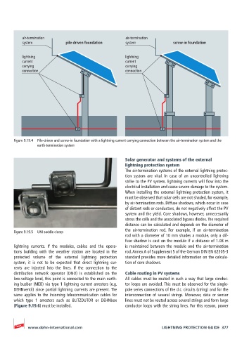
air-termination                           air-termination
          system            pile-driven foundation  system              screw-in foundation


          lightning                                 lightning
          current                                   current
          carrying                                  carrying
          connection                                connection


       Figure 9.19.4  Pile-driven and screw-in foundation with a lightning current carrying connection between the air-termination system and the
                earth-termination system

                                                    Solar generator and systems of the external
                                                    lightning protection system
                                                    The air-termination systems of the external lightning protec-
                                                    tion system are vital. In case of an uncontrolled lightning
                                                    strike to the PV system, lightning currents will flow into the
                                                    electrical installation and cause severe damage to the system.
                                                    When installing the external lightning protection system, it
                                                    must be observed that solar cells are not shaded, for example,
                                                    by air-termination rods. Diffuse shadows, which occur in case
                                                    of distant rods or conductors, do not negatively affect the PV
                                                    system and the yield. Core shadows, however, unnecessarily
                                                    stress the cells and the associated bypass diodes. The required
                                                    distance can be calculated and depends on the diameter of
                                                    the air-termination rod. For example, if an air-termination
       Figure 9.19.5  UNI saddle clamp
                                                    rod with a diameter of 10 mm shades a module, only a dif-
                                                    fuse shadow is cast on the module if a distance of 1.08 m
       lightning  currents.  If  the  modules,  cables  and  the  opera-  is maintained between the module and the air-termination
       tions building with the weather station are located in the   rod. Annex A of Supplement 5 of the German DIN EN 62305-3
       protected volume of the external lightning protection   standard provides more detailed information on the calcula-
       system, it is not to be expected that direct lightning cur-  tion of core shadows.
       rents  are  injected  into  the  lines.  If  the  connection  to  the
       distribution  network  operator  (DNO) is  established  on the   Cable routing in PV systems
       low-voltage level, this point is connected to the main earth-  All cables must be routed in such a way that large conduc-
       ing busbar (MEB) via type 1 lightning current arresters (e.g.    tor loops are avoided. This must be observed for the single-
       DEHNventil) since partial lightning currents are present. The   pole series connections of the d.c. circuits (string) and for the
       same applies to the incoming telecommunication cables for   interconnection of several strings. Moreover, data or sensor
       which type 1 arresters such as BLITZDUTOR or DEHNbox    lines must not be routed across several strings and form large
       (Figure 9.19.6) must be installed.           conductor loops with the string lines. For this reason, power


            www.dehn-international.com                             LIGHTNING PROTECTION GUIDE  377