
Page 39 - 35_DS702_E_2014_Lightning_Protection_Guide
P. 39
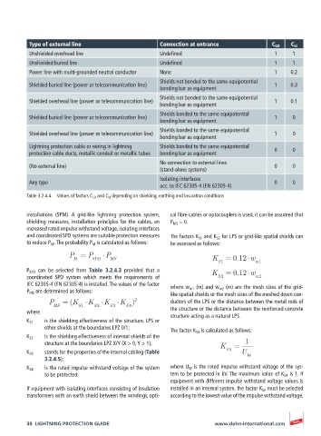
Type of external line                     Connection at entrance             C LD  C LI
          Unshielded overhead line                  Undefined                           1     1
          Unshielded buried line                    Undefined                           1     1
          Power line with multi-grounded neutral conductor  None                        1    0.2
                                                    Shields not bonded to the same equipotential
          Shielded buried line (power or telecommunication line)                        1    0.3
                                                    bonding bar as equipment
                                                    Shields not bonded to the same equipotential
          Shielded overhead line (power or telecommunication line)                      1    0.1
                                                    bonding bar as equipment
                                                    Shields bonded to the same equipotential
          Shielded buried line (power or telecommunication line)                        1     0
                                                    bonding bar as equipment
                                                    Shields bonded to the same equipotential
          Shielded overhead line (power or telecommunication line)                      1     0
                                                    bonding bar as equipment
          Lightning protection cable or wiring in lightning    Shields bonded to the same equipotential    0  0
          protection cable ducts, metallic conduit or metallic tubes  bonding bar as equipment
                                                    No connection to external lines
          (No external line)                                                            0     0
                                                    (stand-alone systems)
                                                    Isolating interfaces
          Any type                                                                      0     0
                                                    acc. to IEC 62305-4 (EN 62305-4)
          Table 3.2.4.4  Values of factors C LD  and C LI  depending on shielding, earthing and insulation conditions


          installations  (SPM).  A  grid-like  lightning  protection  system,   cal fibre cables or optocouplers is used, it can be assumed that
          shielding measures, installation principles for the cables, an   P MS  = 0.
          increased rated impulse withstand voltage, isolating interfaces
          and coordinated SPD systems are suitable protection measures   The factors K S1  and K S2  for LPS or grid-like spatial shields can
          to reduce P M  . The probability P M  is calculated as follows:  be assessed as follows:

                       P = P       P
                        M     SPD   MS                              K    = 0.12 w
                                                                      S1          m1
          P SPD   can  be  selected  from  Table  3.2.4.3  provided  that  a   K  = 0.12 w
          coordinated SPD system which meets the requirements of      S 2         m2
          IEC 62305-4 (EN 62305-4) is installed. The values of the factor   where w m1  (m) and w m2  (m) are the mesh sizes of the grid-
          P MS  are determined as follows:
                                                       like spatial shields or the mesh sizes of the meshed down con-
                 P   = (K    K    K    K )  2          ductors of the LPS or the distance between the metal rods of
                  MS      S1   S 2  S 3  S 4           the structure or the distance between the reinforced concrete
          where                                        structure acting as a natural LPS.
          K S1    is the shielding effectiveness of the structure, LPS or
               other shields at the boundaries LPZ 0/1;
                                                       The factor K S4  is calculated as follows:
          K S2    is the shielding effectiveness of internal shields of the
               structure at the boundaries LPZ X/Y (X > 0, Y > 1);     K   =   1
          K S3    stands for the properties of the internal cabling (Table     S 4  U
               3.2.4.5);                                                       W
          K S4    is the rated impulse withstand voltage of the system   where U W  is the rated impulse withstand voltage of the sys-
               to be protected.                        tem to be protected in kV. The maximum value of K S4  is 1. If
                                                       equipment with different impulse withstand voltage values is
          If equipment with isolating interfaces consisting of insulation   installed in an internal system, the factor K S4  must be selected
          transformers with an earth shield between the windings, opti-  according to the lowest value of the impulse withstand voltage.


          38  LIGHTNING PROTECTION GUIDE                             www.dehn-international.com