
Page 40 - 35_DS702_E_2014_Lightning_Protection_Guide
P. 40
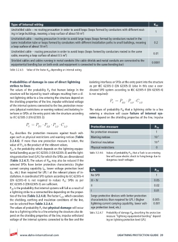
Type of internal wiring                                                           K S3
       Unshielded cable – no routing precaution in order to avoid loops (loops formed by conductors with different rout-  1
                                                2
       ing in large buildings, meaning a loop surface of about 50 m )
       Unshielded cable – routing precaution in order to avoid large loops (loops formed by conductors routed in the
       same installation tube or loops formed by conductors with different installation paths in small buildings, meaning   0.2
       a loop surface of about 10 m )
                           2
       Unshielded cable – routing precaution in order to avoid loops (loops formed by conductors routed in the same
                                      2
       cable, meaning a loop surface of about 0.5 m )                                    0.01
       Shielded cables and cables running in metal conduits (the cable shields and metal conduits are connected to the   0.0001
       equipotential bonding bar on both ends and equipment is connected to the same bonding bar)
       Table 3.2.4.5  Value of the factor K S3  depending on internal wiring


       Probabilities of damage in case of direct lightning   isolating interfaces or SPDs at the entry point into the structure
       strikes to lines                             as per IEC 62305-3 (EN 62305-3) (also in this case a coor-
       The values of the probability P U  that human beings in the   dinated SPD system according to IEC 62305-4 (EN 62305-4)
       structure will be injured by touch voltages resulting from a di-  is not required):
       rect lightning strike to a line entering the structure depend on
       the shielding properties of the line, impulse withstand voltage   P = P EB  P LD  C LD
                                                                 V
       of the internal systems connected to the line, protection meas-
       ures (physical restrictions or warning notices) and isolating in-  The values of probability P W  that a lightning strike to a line
       terfaces or SPDs at the entry point into the structure according   entering a structure will cause  failure of internal sys-
       to IEC 62305-3 (EN 62305-3):                 tems depend on the shielding properties of the line, impulse

                P = P     P    P    C
                 U     TU   EB   LD   LD             Protection measure                   P TU
       P TU  describes the protection measures against touch volt-  No protection measure  1
       ages such as physical restrictions and warning notices (Table   Warning notices    10 -1
       3.2.4.6). If more than one protection measure is taken, the   Electrical insulation  10 -2
       value of P TU  is the product of the relevant values.
       P EB  is the probability which depends on the lightning equipo-  Physical restrictions  0
       tential bonding as per IEC 62305-3 (EN 62305-3) and the light-  Table 3.2.4.6  Values of probability P TU  that a flash to an entering
       ning protection level (LPL) for which the SPDs are dimensioned   line will cause electric shock to living beings due to
       (Table 3.2.4.7). The values of P EB  may also be reduced if the   dangerous touch voltages
       selected SPDs have better protection characteristics (higher
       current carrying capability I N  , lower voltage protection level   LPL
       U P  , etc.) than required for LPL I at the relevant places of in-                 P EB
       stallation. A coordinated SPD system according to IEC 62305-4     No SPD           1
       (EN 62305-4) is not required to reduce P U  ; SPDs as per     III – IV            0.05
       IEC 62305-3 (EN 62305-3) are sufficient.      II                                  0.02
       P LD  is the probability that internal systems will fail as a result of
       a lightning strike to a connected line depending on the proper-  I                0.01
       ties of the line (Table 3.2.4.8). The factor C LD  , which considers   Surge protective devices with better protection
       the shielding, earthing and insulation conditions of the line,   characteristics than required for LPL I (higher   0.005 –
       can be selected from Table 3.2.4.4.           lightning current carrying capability, lower volt-  0.001
       The values of probability P V  that physical damage will occur   age protection level, etc.)
       due to a lightning strike to a line entering the structure also de-  Table 3.2.4.7  Probability of damage P EB  describing the protection
       pend on the shielding properties of the line, impulse withstand   measure “lightning equipotential bonding” depend-
       voltage of the internal systems connected to the line and the   ing on lightning protection level (LPL)


            www.dehn-international.com                              LIGHTNING PROTECTION GUIDE  39