
Page 41 - 35_DS702_E_2014_Lightning_Protection_Guide
P. 41
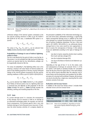
Line type  Routing, shielding and equipotential bonding   Impulse withstand voltage U W  in kV
                                                                     1     1.5   2.5    4     6
                    Overhead or buried line, unshielded or shielded, whose shield is not
          Power or   bonded to the same equipotential bonding bar as the equipment  1  1  1  1  1
          telecom-                               5 Ω/km < RS ≤ 20 Ω/km  1   1    0.95  0.9   0.8
          munication   Shielded overhead or buried line whose
          lines     shield is bonded to the same equipo-  1 Ω/km < RS ≤ 5 Ω/km  0.9  0.8  0.6  0.3  0.1
                    tential bonding bar as the equipment  RS ≤ 1 Ω/km  0.6  0.4  0.2   0.04  0.02

          Table 3.2.4.8  Values of the probability P LD  depending on the resistance of the cable shield R S  and the impulse withstand voltage U W  of the
                   equipment

          withstand voltage of the internal systems connected to the   the permanent availability of the information technology sys-
          line and the isolating interfaces or SPDs as per IEC 62305-4    tem (call centre, bank, automation technology), a significantly
          (EN 62305-4) (in this case, a coordinated SPD system is re-  higher consequential damage occurs in addition to the hard-
          quired):                                     ware damage (e.g. customer dissatisfaction, loss of customers,
                                                       loss of business, production downtime). The loss L (this term
                     P = P      P    C                 used in IEC 62305-2 (EN 62305-2) is an unfortunate choice;
                      W     SPD  LD    LD
                                                       damage factor or loss value would be more appropriate) al-
          The values of P EB  , P SPD  , P LD  and C LD  can be selected from     lows to assess the consequences of damage. In this context,
          Tables 3.2.4.3, 3.2.4.4, 3.2.4.7 and 3.2.4.8.  losses are subdivided according to the types of damage (D1
                                                       to D3):
          Probabilities of damage in case of indirect lightning   L t    Loss due to injuries caused by electric shock resulting
          strikes to lines                                   from touch and step voltages (D1);
          The line is not directly hit; the point of strike is near the line. In   L f    Loss due to physical damage (D2);
          this process, it can be excluded that high-level partial lightning
          currents are injected into the line. Nevertheless, voltages can   L o    Loss due to the failure of electrical and electronic sys-
          be magnetically induced on the line.               tems (D3).
                                                       Depending on the type of loss L1 to L4, the extent, costs
          The values of probability P Z  that lightning strikes near a line   and consequences of damage are assessed. Annex C of the
          entering a structure will cause failure of internal systems de-  IEC 62305-2 (EN 62305-2) standard includes the calculation
          pend on the shielding properties of the line, impulse withstand   bases for the loss of the four types of loss. In the next sections,
          voltage of the internal systems connected to the line and the   this loss will be shortly described after the reduction and in-
          isolating interfaces or SPDs as per IEC 62305-4 (EN 62305-4):  crease factors and the parameters and equations for the differ-
                                                       ent zones of a structure will be defined. However, all structures
                     P = P      P   C                  can also be described by a single zone, meaning that the entire
                      Z     SPD   LI  LI
                                                       structure consists of one zone.
          P SPD  can be selected from Table 3.2.4.3. P LI  is the probabil-
          ity of failure of internal systems due to a lightning strike near   Reduction and increase factors
          a connected line and depends on the properties of the line    In addition to the actual loss factors, Annex C includes three
          (Table 3.2.4.9). The factor C LI  (Table 3.2.4.4) considers the   reduction factors and one increase factor:
          shielding, earthing and insulating properties of the line.
                                                                           Impulse withstand voltage
                                                             Line type            U W  in kV
          3.2.5  Loss
                                                                           1  1.5  2.5   4    6
          If a certain damage occurs in a structure, the consequences   Power lines  1  0.6  0.3  0.16  0.1
          of this damage must be assessed. A fault on or damage to
          an information technology system, for example, can have dif-  Telecommunication lines  1  0.5  0.2  0.08  0.04
          ferent consequences. If no business-specific data is lost, only   Table 3.2.4.9  Values of the probability P LI  depending on the line
          hardware damage of some thousand euros may occur. If, how-  type and the impulse withstand voltage U W  of the
          ever, the entire business activities of a company depend on   equipment


          40  LIGHTNING PROTECTION GUIDE                             www.dehn-international.com