
Page 55 - 35_DS702_E_2014_Lightning_Protection_Guide
P. 55
¨ Mutual conductance: Conductance between two Almost equal earth resistances (type B earth-termination sys-
points (example: Conductance between two opposite tem) form the basis for this type of calculation of separation
points (clamping points) of a mesh on a flat roof (without distances for a lightning protection system.
branches)). The following steps are required to calculate
the separation distances in case of a building with external
lightning protection system (see also Figure 3.3.2.1.5): 3.3.2.2 Information on the DEHN Distance Tool
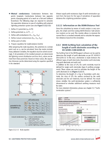
1. Define 0 V potentials (ϕ 0 in P0) Since the calculation by means of nodal analysis is very com-
plex, the simple and time-saving DEHN Distance Tool calcula-
2. Define potentials (ϕ 1 in P1, …)
tion module can be used. This module allows to simulate the
3. Define self-conductances (G 11 , G 22 , G nn ) current flow in a meshed network and to calculate the separa-
4. Define mutual conductances (G 12 , G 23 , G nm ) tion distances based on this simulation.
5. Define point of strike
6. Prepare equations for nodal analysis (matrix) 3.3.3 DEHN Earthing Tool; calculation of the
After preparing the node equations, the potential at a certain length of earth electrodes according to
point such as ϕ 1 can be calculated. Since the matrix includes IEC 62305-3 (EN 62305-3)
many unknown variables, the equation must be solved accord-
ingly. If all potentials of the meshed network are determined, The Earthing Tool of the DEHNsupport software can be used to
the lightning current distribution and thus the k c values are de- determine the length of earth electrodes as per IEC 62305-3
rived from these potentials. Based on these values, the separa- (EN 62305-3). To this end, a distinction is made between the
tion distances can be determined using the equation specified different types of earth electrodes (foundation earth electrode,
ring earth electrode and earth rod).
in the standard.
In addition to the class of LPS, the earth resistivity must be
defined for single earth electrodes (type A earthing arrange-
ment). These values are used to calculate the length of the
P0 G 12 = G 21 P0 earth electrode (in m) (Figure 3.3.3.1).
To determine the length of a ring or foundation earth elec-
P1 G 11 P2 G 22 P3 G 33
trode, the class of LPS, the surface enclosed by the earth
electrode and the soil resistivity must be defined. The result
shows whether the earth-termination system is sufficiently
dimensioned or whether additional earthing measures must
P4 G 44 P5 G 55 P6 G 66
be taken.
For more detailed information, please see chapter 5.5 “Earth-
termination systems”.
P7 G 77 P8 G 88 P9 G 99
P0 node P0
self-conductance
G 11 – G 12 – G 13 – G 1m ϕ 1 I 1
potential to be G 21 – G 22 – G 23 – G 2m ϕ 2 I 2
calculated ϕ 1 : G 31 – G 32 – G 33 – G 3m ϕ 3 I 3
G n1 – G n2 – G n3 – G nm ϕ n I n
mutual conductance
mutual conductance G 12 = mutual conductance G 21
G 11 = self-conductance
(sum of G 12 + G 14 + G 10 )
ϕ 1 = node potential in point P1
I 1 = partial lightning current in point P1
Figure 3.3.2.1.5 Node equation Figure 3.3.3.1 DEHN Earthing Tool, type A earth-termination system
54 LIGHTNING PROTECTION GUIDE www.dehn-international.com