
Page 76 - 35_DS702_E_2014_Lightning_Protection_Guide
P. 76
and destruction described before. To prevent this, antennas
are equipped with isolated air-termination systems (e.g. air-
termination rods) (Figure 5.1.2.5).
Air-termination systems on the ridge have a tent-shaped pro-
tected volume (according to the protective angle method). The
angle depends on the height above the reference plane (e.g.
surface of the earth) and the selected class of LPS.
5.1.3 Air-termination systems for buildings
with flat roofs
The mesh method is used to design an air-termination system
for buildings with flat roofs (Figure 5.1.3.1). A meshed air-
termination network with a mesh size according to the class of Figure 5.1.3.2 Practical use of air-termination rods
LPS is arranged on the roofing (Table 5.1.1.3).
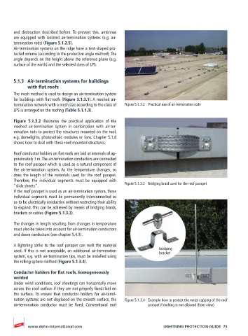
Figure 5.1.3.2 illustrates the practical application of the
meshed air-termination system in combination with air-ter-
mination rods to protect the structures mounted on the roof,
e.g. domelights, photovoltaic modules or fans. Chapter 5.1.8
shows how to deal with these roof-mounted structures.
Roof conductor holders on flat roofs are laid at intervals of ap-
proximately 1 m. The air-termination conductors are connected
to the roof parapet which is used as a natural component of
the air-termination system. As the temperature changes, so
does the length of the materials used for the roof parapet.
Therefore, the individual segments must be equipped with
“slide sheets”. Figure 5.1.3.3 Bridging braid used for the roof parapet
If the roof parapet is used as an air-termination system, these
individual segments must be permanently interconnected so
as to be electrically conductive without restricting their ability
to expand. This can be achieved by means of bridging braids,
brackets or cables (Figure 5.1.3.3).
The changes in length resulting from changes in temperature
must also be taken into account for air-termination conductors
and down conductors (see chapter 5.4.1).
A lightning strike to the roof parapet can melt the material
used. If this is not acceptable, an additional air-termination bridging
bracket
system, e.g. with air-termination tips, must be installed using
the rolling sphere method (Figure 5.1.3.4).
Conductor holders for flat roofs, homogeneously
welded
Under wind conditions, roof sheetings can horizontally move
across the roof surface if they are not properly fixed / laid on
the surface. To ensure that conductor holders for air-termi-
nation systems are not displaced on the smooth surface, the Figure 5.1.3.4 Example how to protect the metal capping of the roof
air-termination conductor must be fixed. Conventional roof parapet if melting is not allowed (front view)
www.dehn-international.com LIGHTNING PROTECTION GUIDE 75