
Page 87 - 35_DS702_E_2014_Lightning_Protection_Guide
P. 87
More detailed information (e.g. installation, assembly) on Conductors or cables can also be dimensioned using the roll-
these steel telescopic lightning protection masts can be found ing sphere method (radius of the rolling sphere according to
in installation instructions No. 1729 (Figures 5.1.8.8). the class of LPS).
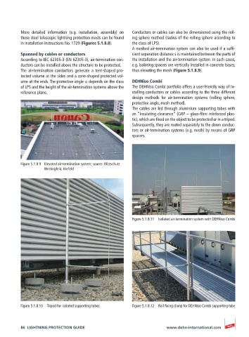
A meshed air-termination system can also be used if a suffi-
Spanned by cables or conductors cient separation distance s is maintained between the parts of
According to IEC 62305-3 (EN 62305-3), air-termination con- the installation and the air-termination system. In such cases,
ductors can be installed above the structure to be protected. e.g. isolating spacers are vertically installed in concrete bases,
The air-termination conductors generate a tent-shaped pro- thus elevating the mesh (Figure 5.1.8.9).
tected volume at the sides and a cone-shaped protected vol-
ume at the ends. The protective angle α depends on the class DEHNiso Combi
of LPS and the height of the air-termination systems above the The DEHNiso Combi portfolio offers a user-friendly way of in-
reference plane. stalling conductors or cables according to the three different
design methods for air-termination systems (rolling sphere,
protective angle, mesh method).
The cables are led through aluminium supporting tubes with
an “insulating clearance” (GRP – glass-fibre reinforced plas-
tic), which are fixed on the object to be protected or in a tripod.
Subsequently, they are routed separately to the down conduc-
tors or air-termination systems (e.g. mesh) by means of GRP
spacers.
Figure 5.1.8.9 Elevated air-termination system; source: Blitzschutz
Wettingfeld, Krefeld
Figure 5.1.8.11 Isolated air-termination system with DEHNiso Combi
Figure 5.1.8.10 Tripod for isolated supporting tubes Figure 5.1.8.12 Rail fixing clamp for DEHNiso Combi supporting tube
86 LIGHTNING PROTECTION GUIDE www.dehn-international.com