
Page 84 - 35_DS702_E_2014_Lightning_Protection_Guide
P. 84
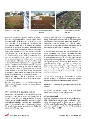
Figure 5.1.7.1  Green roof   Figure 5.1.7.2  Air-termination system on a   Figure 5.1.7.3  Conductor routing above the
                                              green roof                    cover layer


       If a meshed air-termination system is used, the IEC 62305-3   According to the state of the art of lightning protection tech-
       (EN 62305-3) lightning protection standard requires a mesh   nology, such roof-mounted structures are protected against
       size which depends on the relevant class of LPS (see chapter   direct lightning strikes by means of separately mounted air-
       5.1.1, Table 5.1.1.3). An air-termination conductor installed   termination systems. This prevents partial lightning  currents
       inside the cover layer is difficult to inspect after some years   from entering the building where they would interfere with or
       because the air-termination tips or studs are overgrown and   even destroy sensitive electrical / electronic equipment.
       no longer recognisable and frequently damaged during main-
       tenance work. Moreover, air-termination conductors installed   In the past, these roof-mounted structures were directly con-
       inside the cover layer are susceptible to corrosion. Conduc-  nected so that parts of the lightning current were conducted
       tors of air-termination meshes installed evenly on top of the   into the building. Later, roof-mounted structures were indirect-
       cover layer are easier to inspect even if they are overgrown   ly connected via a spark gap. This meant that direct lightning
       and the air-termination system can be elevated by means of   strikes to the roof-mounted structure could still flow through
       air-termination tips and rods and thus “grow” with the plants   the “internal conductor” although the spark gap should not
       on the roof. Air-termination systems can be designed in differ-  reach the sparkover voltage in the event of a more remote
       ent ways. A meshed air-termination network with a mesh size   lightning strike to the building. This voltage of approximately
       of 5 m x 5 m (class of LPS I) up to a maximum mesh size of   4 kV was almost always reached and thus partial lightning
       15 m x 15 m (class of LPS III) is typically installed on the roof   currents were also injected into the building via the electrical
       surface, regardless of the height of the building. The mesh is to   cable, for example, which led to interference with the electrical
       be preferably installed on the external edges of the roof and on   or electronic installations.
       any metal structures serving as air-termination system.
       Stainless steel (V4A, e.g. material No. AISI/ASTM 316 Ti) has   The only way of preventing that these currents are injected
       proven to be a good wire material for air-termination systems   into the building is to use isolated air-termination systems
       on green roofs.                              which ensure that the separation distance s is maintained.
       Aluminium wires must not be used for installing conductors in
       the cover layer (in the earth substrate or granulate) (Figures   Figure 5.1.8.1 shows partial lightning currents entering the
       5.1.7.1 to 5.1.7.3).                         structure.

                                                    The different roof-mounted structures can be protected by
       5.1.8  Isolated air-termination systems      various types of isolated air- termination systems.
       Roof-mounted structures such as air-conditioning and cool-
       ing systems, e.g. for mainframes, are frequently installed on   Air-termination rods
       the roofs of large office and industrial buildings. These roof-  Small roof-mounted structures (e.g. small fans) can be protect-
       mounted systems must be treated like antennas, electrically   ed by individual air-termination rods or a combination of sev-
       controlled domelights, advertising signs with integrated light-  eral air-termination rods. Air-termination rods up to a height
       ing and all other protruding roof-mounted structures because   of 2.0 m can be fixed by means of one or two concrete bases
       they typically have a conductive connection into the building,   piled on top of each other (e.g. Part No. 102 010) so that they
       e.g. via electrical lines or ducts.          are isolated (Figure 5.1.8.2).


            www.dehn-international.com                              LIGHTNING PROTECTION GUIDE  83