
Page 82 - 35_DS702_E_2014_Lightning_Protection_Guide
P. 82
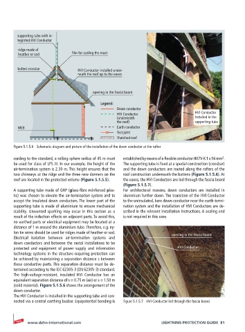
supporting tube with in-
        tegrated HVI Conductor
         ridge made of
         heather or sod        film for sealing the mast

        bolted crossbar          HVI Conductor installed under-
                                 neath the roof up to the eaves


                                        opening in the fascia board

                                           Legend:
                                                  Down conductor
                                                  HVI Conductor                   HVI Conductor
                                                  (underneath                     installed in the
                                                  the roof)                       supporting tube
        MEB                                       Earth conductor
                                                  Test joint
                                                  Thatched roof

       Figure 5.1.5.6  Schematic diagram and picture of the installation of the down conductor at the rafter
                                                                                              2
       cording to the standard, a rolling sphere radius of 45 m must   established by means of a flexible conductor H07V-K 1 x 16 mm .
       be used for class of LPS III. In our example, the height of the   The supporting tube is fixed at a special construction (crossbar)
       air-termination system is 2.30 m. This height ensures that the   and the down conductors are routed along the rafters of the
       two chimneys at the ridge and the three new dormers on the   roof construction underneath the battens (Figure 5.1.5.6). At
       roof are located in the protected volume (Figure 5.1.5.5).  the eaves, the HVI Conductors are led through the fascia board
                                                    (Figure 5.1.5.7).
       A supporting tube made of GRP (glass-fibre reinforced plas-  For architectural reasons, down conductors are installed in
       tic) was chosen to elevate the air-termination system and to   aluminium further down. The transition of the HVI Conductor
       accept the insulated down conductors. The lower part of the   to the uninsulated, bare down conductor near the earth-termi-
       supporting tube is made of aluminium to ensure mechanical   nation system and the installation of HVI Conductors are de-
       stability. Unwanted sparking may occur in this section as a   scribed in the relevant installation instructions. A sealing end
       result of the induction effects on adjacent parts. To avoid this,   is not required in this case.
       no earthed parts or electrical equipment may be located at a
       distance of 1 m around the aluminium tube. Therefore, e.g. ny-
       lon tie wires should be used for ridges made of heather or sod.  opening in the fascia board
       Electrical  isolation between air-termination  systems and
       down conductors and between the metal installations to be
       protected and equipment of power supply and information             HVI Conductor
       technology systems in the structure requiring protection can
       be achieved by maintaining a separation distance s between
       these conductive parts. This separation distance must be de-
       termined according to the IEC 62305-3 (EN 62305-3) standard.
       The high-voltage-resistant, insulated HVI Conductor has an
       equivalent separation distance of s = 0.75 m (air) or s = 1.50 m
       (solid material). Figure 5.1.5.6 shows the arrangement of the
       down conductor.
       The HVI Conductor is installed in the supporting tube and con-
       nected via a central earthing busbar. Equipotential bonding is   Figure 5.1.5.7  HVI Conductor led through the fascia board


            www.dehn-international.com                              LIGHTNING PROTECTION GUIDE  81