
Page 102 - 35_DS702_E_2014_Lightning_Protection_Guide
P. 102
sphere method are ideally positioned. These structures are ¨ Prevention of creeping discharge
typically connected to the technical equipment of the building. ¨ Sufficient current carrying capability thanks to a sufficient
Discharging the lightning current to earth while maintaining cross-sectional area of the down conductor
a sufficient separation distance s and ensuring the aesthetical
appearance of the building is a special challenge. HVI (High ¨ Lightning current carrying connection of the down conduc-
Voltage Insulation) Conductors are an ideal solution. tor to the air-termination system (air-termination rod, air-
termination conductor, etc.)
Separation distance ¨ Connection to the earth-termination or equipotential bond-
The calculation of the separation distance forms the basis for ing system
the decision whether and which HVI Conductor can be used for If certain high-voltage boundary conditions are fulfilled, the
the installation. Consequently, the design of an isolated light- separation distance s can be maintained by covering the
ning protection system is based on the separation distance. To down conductor with insulating materials with a high electric
be able to take adequate protection measures, the separation strength. However, possible creeping discharge must be pre-
distance must be already calculated at the design stage. Chap- vented! This problem cannot be solved by using a conductor
ter 5.6 gives a detailed description of the different calculation which is covered with insulating materials only.
options for determining the separation distance. The absolute Creeping discharge near proximities (e.g. between earthed
conductor lengths are decisive for calculating the separation metal conductor holders and the feed point), which may lead
distance particularly in case of HVI Conductors. According to to an overall flashover at the surface over great conductor
IEC 62305-3 (EN 62305-3), the separation distance s for pre- lengths, already occurs in case of relatively low impulse volt-
venting uncontrolled flashover is calculated as follows: ages.
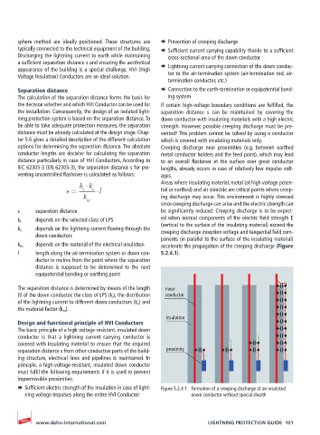
k k Areas where insulating material, metal (at high voltage poten-
s = i c l tial or earthed) and air coincide are critical points where creep-
k ing discharge may occur. This environment is highly stressed
m
since creeping discharge can arise and the electric strength can
s separation distance be significantly reduced. Creeping discharge is to be expect-
k i depends on the selected class of LPS ed when normal components of the electric field strength E
(vertical to the surface of the insulating material) exceed the
k c depends on the lightning current flowing through the creeping discharge inception voltage and tangential field com-
down conductors
ponents (in parallel to the surface of the insulating material)
k m depends on the material of the electrical insulation accelerate the propagation of the creeping discharge (Figure
l length along the air-termination system or down con- 5.2.4.1).
ductor in metres from the point where the separation
distance is supposed to be determined to the next
equipotential bonding or earthing point
The separation distance is determined by means of the length inner
(l) of the down conductor, the class of LPS (k i ), the distribution conductor
of the lightning current to different down conductors (k c ) and
the material factor (k m ).
insulation
Design and functional principle of HVI Conductors
The basic principle of a high-voltage-resistant, insulated down
conductor is that a lightning current carrying conductor is
covered with insulating material to ensure that the required
separation distance s from other conductive parts of the build- proximity
ing structure, electrical lines and pipelines is maintained. In
principle, a high-voltage-resistant, insulated down conductor
must fulfil the following requirements if it is used to prevent
impermissible proximities:
¨ Sufficient electric strength of the insulation in case of light- Figure 5.2.4.1 Formation of a creeping discharge at an insulated
ning voltage impulses along the entire HVI Conductor down conductor without special sheath
www.dehn-international.com LIGHTNING PROTECTION GUIDE 101