Page 99 - ABB_Motor _Protection_and_Control_catalogue_20221216
P. 99

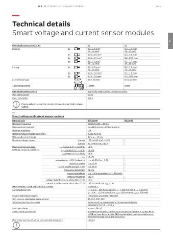
ABB  MOTOR PROTECTION AND CONTROL                                                3/23
          —


          Technical details


          Smart voltage and current sensor modules


                                                                                                                      03
          Electrical connection X1, X3                       X1                        X3
          Push-In                               1x           0.2...2.5 mm   2          0.2...1.5 mm   2
                                                             24...12 AWG               24...16 AWG
                                                1x           0.25...2.5 mm  2          0.2...1.5 mm 2
                                                1x           0.25...2.5 mm  2          0.2...0.75 mm 2
                                                1x           0.2...2.5 mm 2            0.2...1.5 mm²
                                                             24...12 AWG               24...16 AWG
          Spring                                1x           0.2...2.5 mm   2          0.2...1.5 mm   2
                                                             24...12 AWG               24...16 AWG
                                                1x           0.25...2.5 mm  2          0.2...1.5 mm 2
                                                1x           0.25...2.5 mm  2          0.2...0.75 mm 2
          Screwdriver type                                   0.6 x 3.5 mm              0.4 x 2.5 mm
          Tightening torque                                  10 mm                     8 mm

          Electrical connection X2                           use ready-made cables, see accessories.
          Max cable length                                   0.5 m
          Basic insulation                                   300 V
                Ensure safe distance from motor wires and other high voltage
                cables.

          —
          Smart voltage and current sensor modules
          Input circuit                                      SCV10-40                  SC10-40
          Nominal frequency                                  50/60 Hz (45 ... 65 Hz)
          Measurement method                                 true RMS (up to 13th harmonics)
          Number of phases                                   1/3
          Nominal measuring range current                    0.2 to 40 A AC
          Measured current range                             0.2 x I e … 15 x I e
          Nominal voltage range                                                                                        3 phase  150 to 690 V AC ± 10 %  -
                                                      1 phase  90 to 400 V AC ±10 %    -
          Measurement accuracy            I rms (range 0.2 * I e ≤ 0.75*I e)  ±3 %
          given at Ta=25 °C, 50/60 Hz      I rms (range 0.75 * I e ≤ 2*I e)  ±1,5 %
                                            I rms (range >2 * I e ≤ 15*I e)  ±3 %
                                                         U rms  ±1.5 %                 -
                                       power factor ≥ 0.5  (inductive)  typ. ±1.5% (I rms > 3 A)  -
                                                 apparent power  typ. ±3 %             -
                                         active power (cos phi > 0.5)  typ. ±5 %       -
                                             frequency (50/60 Hz)  ±1.5 %              -
                                               current imbalance  typ ±10 % (condition: I mot > 150 mA)
                                               voltage imbalance  ±10 %                -
                                 voltage total harmonic distortion (THD)  ±5 %         -
                                 current total harmonic distortion (THD)  ±10 % (condition: I mot > 1A)
          Measurement range of earth fault current           > 20% of I e
          Earth fault current                                I e < 1.0 A :    ±25 % (condition: I mot > 100 mA and  I earth  > 80 mA)
                                                             I e >1.0 A :    ±10 % (condition: I mot > 200 mA and  I earth  > 200 mA)
          Supported network types                            1/3 phase, grounded networks
          Trip classes, selectable by parameter              5E, 10E, 20E, 30E
          Tripping time for phase loss                       determined by parameter CurrPhaseLossDelayPar.
                                                             adjustable from 0 … 25.5 s
          Load per phase                                     approx. 30 mΩ
          Short-circuit protection                           provided by external short-circuit protection device, e. g. MO, MCB,
                                                             MCCB or fuse. Refer also to ABB coordination tables available here:
                                                             www.lowvoltage-tools.abb.com/soc/
          Max cross-section of wires. Use isolated wires only!  16 mm 2
   94   95   96   97   98   99   100   101   102   103   104