
Page 561 - Din prodcuts 2020
P. 561
5/117
—
Protection and safety
Data & signal protection
OVR SL LED 4-20 mA Series
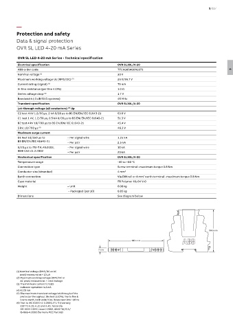
OVR SL LED 4-20 mA Series - Technical specification
Electrical specification OVR SL30L/4-20
ABB order code 7TCA085400R0371 5
Nominal voltage (1) 30 V
Maximum working voltage Uc (RMS/DC) (2) 25 V/36.7 V
Current rating (signal) (3) 75 mA
In-line resistance (per line ±10%) 1.0 Ω
Series voltage drop (4) 1.7 V
Bandwidth (-3 dB 50 Ω systems) 45 MHz
Transient specification OVR SL30L/4-20
Let-through voltage (all conductors) Up
(5)
C2 test 4 kV 1.2/50 μs, 2 kA 8/20 μs to BS EN/EN/IEC 61643-21 63.0 V
C1 test 1 kV, 1.2/50 μs, 0.5 kA 8/20 μs to BS EN/EN/IEC 61643-21 51.3 V
B2 test 4 kV 10/700 μs to BS EN/EN/IEC 61643-21 45.4 V
5 kV, 10/700 μs (6) 46.3 V
Maximum surge current
D1 test 10/350 μs to – Per signal wire 1.25 kA
BS EN/EN/IEC 61643-21
– Per pair 2.5 kA
8/20 μs to ITU-T K.45:2003, – Per signal wire 10 kA
IEEE C62.41.2:2002
– Per pair 20 kA
Mechanical specification OVR SL30L/4-20
Temperature range -40 to +80 °C
Connection type Screw terminal - maximum torque 0.8 Nm
Conductor size (stranded) 4 mm 2
Earth connection Via DIN rail or 4 mm earth terminal - maximum torque 0.8 Nm
2
Case material FR Polymer UL-94 V-0
Weight – Unit 0.08 kg
– Packaged (per 10) 0.85 kg
Dimensions See diagram below
104.6 mm
106.5 mm
7 mm 2 S 1 1 S 2 E
(1) Nominal voltage (RMS/DC or AC
peak) measured at < 10 μA
(2) Maximum working voltage (RMS/DC or
AC peak) measured at < 1 mA leakage
(3) The minimum current for LED
indicator operation is 2 mA
(4) At 20 mA
(5) The maximum transient voltage let-through of the
protector throughout the test (±10%), line to line &
line to earth, both polarities. Response time < 10 ns
(6) Test to IEC 61000-4-5:2006, ITU-T (formerly
CCITT) K.20, K.21 and K.45, Telcordia
GR-1089-CORE, Issue 2:2002, ANSI TIA/EIA/
IS-968-A:2002 (formerly FCC Part 68)