
Page 103 - 35_DS702_E_2014_Lightning_Protection_Guide
P. 103
ing end range depends on the type of HVI Conductor. This spe-
connection to the
air-termination system cial sealing end begins at the feed point (connection to the air-
sealing end range termination system) and ends with the equipotential bonding
injection of lightning connection element at a defined distance (Figure 5.2.4.3).
impulse current
inner conductor semiconductive Based on the necessary separation distance s, the maximum
sheath conductor length L max of such an insulated down conductor
high-voltage- can be calculated as follows:
resistant insulation connection to the equi-
potential bonding system k s
L = m
Figure 5.2.4.2 Components of a HVI Conductor max k k
i c
Types of HVI Conductors
The creeping discharge inception voltage defines the resist-
ance of the entire insulation arrangement and has a lightning HVI Conductors were adapted to meet the constantly growing
impulse voltage between 250 and 300 kV for such arrange- requirements on the installation environment. Three types of
ments. HVI Conductors are available:
¨ HVI light Conductor, DEHNcon-H
Coaxial cables with semi-conductive sheath ¨ HVI Conductor, HVI long Conductor
The specifically developed single-conductor coaxial cable ¨ HVI power Conductor
(HVI Conductor) allows to prevent creeping discharge and to
safely discharge the lightning current to the ground (Figure Each of these types of HVI Conductors (Figure 5.2.4.4) has
5.2.4.2). different thicknesses and characteristics and thus different
Insulated down conductors with field control via a semi- installation requirements. HVI Conductors are available with
conductive sheath prevent creeping discharge by specifically black and grey sheath. The additional grey sheath allows a
influencing the electric field in the sealing end range. Thus, the more aesthetical installation of the HVI Conductor on the rel-
lightning current is led into the special cable and is safely dis- evant building. The most important parameters of the different
charged while maintaining the necessary separation distance s. HVI Conductors are listed in Table 5.2.4.1.
It must be observed that the magnetic field surrounding the
current carrying inner conductor is not interfered with. HVI Conductors fulfil the requirements of the IEC 62561-2
A specially adapted sealing end range of the conductor was (EN 62561-2) standard. In the following, the different types of
created by optimising the field control. The length of this seal- HVI Conductors will be described in detail.
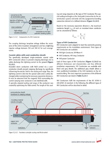
semiconductive sheath field line
(resistance to creeping voltage)
insulating material
(electric strength)
0 V
copper inner
conductor
1.5 m EB connection
head piece element
Figure 5.2.4.3 Functional principle sealing end / field control
102 LIGHTNING PROTECTION GUIDE www.dehn-international.com