
Page 106 - 35_DS702_E_2014_Lightning_Protection_Guide
P. 106
HVI power Conductor (s ≤ 0.9 m in air, s ≤ 1.8 m in
case of solid material)
The HVI power Conductor is the most powerful type of high-
voltage-resistant, insulated HVI Conductors. Compared to the
standard HVI Conductor, an equivalent separation distance of
0.9 m in air and 1.8 m in case of solid material can be main-
tained. The HVI power Conductor and the associated compo-
nents are tested for a lightning current carrying capability up
to 200 kA (10/350 µs) and can therefore be used for all classes
of LPS (I – IV).
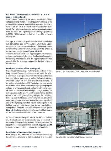
This type of conductor is particularly installed for buildings
such as hospitals, data centres and silos where large separa-
tion distances must be maintained due to the building dimen-
sions (heights). Moreover, it allows larger conductor lengths to
the earth-termination system (Figure 5.2.4.10).
The conductor is installed in the supporting tube. An integrated
spring contact automatically establishes functional equipoten-
tial bonding for the sealing end. The supporting tube must be
connected to the functional equipotential bonding system of
the structure.
Functional principle of the sealing end
High impulse voltages cause flashover at the surfaces of insu- Figure 5.2.4.9 Installation of a HVI Conductor III with sealing end
lating material if no additional measures are taken. This effect
is also known as creeping flashover. If the creeping discharge
inception voltage is exceeded, a surface discharge is initiated
which can easily flash over a distance of several metres. To
prevent creeping discharge, HVI Conductors feature a special
outer sheath which allows to discharge high lightning impulse
voltages to a reference potential. For functional reasons, a con-
nection is established in the sealing end range between the
semiconductive outer sheath and the equipotential bonding
system of the building (no lightning voltage). This connection
to the equipotential bonding system can made e.g. on earthed
metal roof-mounted structures located in the protected vol-
ume of the lightning protection system, earthed parts of the
building structure / radio towers that do not carry lightning
voltage or the protective conductor of the low-voltage system.
Figure 5.2.4.3 shows the functional principle of field control
via the semiconductive sheath of the HVI Conductor.
No conductive or earthed parts such as metal conductor hold-
ers, structural parts or reinforcements may be installed in
the sealing end range (area between the head piece and the
equipotential bonding connection element). Figure 5.2.4.11
shows the separation distance s in the form of a cylinder.
Installation of the connection elements
Black and grey HVI Conductors are available. When installing
the connection elements of HVI Conductors, it is important Figure 5.2.4.10 Installation of a HVI power Conductor
www.dehn-international.com LIGHTNING PROTECTION GUIDE 105