
Page 121 - 35_DS702_E_2014_Lightning_Protection_Guide
P. 121
The curve in Figure 5.5.3 shows that the largest portion of
the total earth resistance occurs in the immediate vicinity of
the earth electrode. For example, at a distance of 5 m from the
centre of the sphere, 90 % of the total earth resistance R A has
already been achieved.
Earth resistivity ρ E
The earth resistivity ρ E , which is decisive for the magnitude of
equipotential lines the earth resistance R A of an earth electrode, depends on the
soil composition, moisture in the soil and the temperature. It
can fluctuate within wide limits.
a) Spherical earth electrode b) Spherical earth electrode Values for various types of soil
deep in the ground close to the earth surface
Figure 5.5.4 shows the fluctuation ranges of the earth resis-
Figure 5.5.2 Current flowing out of a spherical earth electrode tivity ρ E for various types of soil.
Seasonal fluctuations
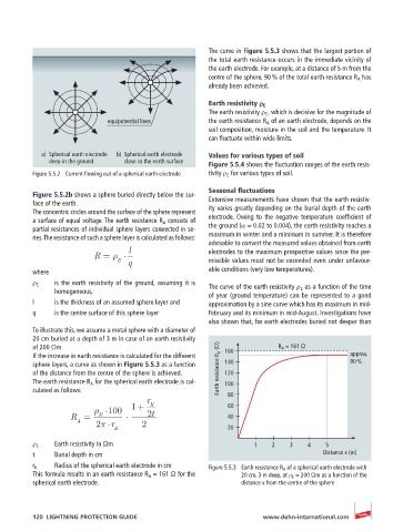
Figure 5.5.2b shows a sphere buried directly below the sur-
face of the earth. Extensive measurements have shown that the earth resistiv-
The concentric circles around the surface of the sphere represent ity varies greatly depending on the burial depth of the earth
a surface of equal voltage. The earth resistance R A consists of electrode. Owing to the negative temperature coefficient of
partial resistances of individual sphere layers connected in se- the ground (α = 0.02 to 0.004), the earth resistivity reaches a
ries. The resistance of such a sphere layer is calculated as follows: maximum in winter and a minimum in summer. It is therefore
advisable to convert the measured values obtained from earth
l electrodes to the maximum prospective values since the per-
R =
E missible values must not be exceeded even under unfavour-
q
where able conditions (very low temperatures).
ρ E is the earth resistivity of the ground, assuming it is The curve of the earth resistivity ρ E as a function of the time
homogeneous, of year (ground temperature) can be represented to a good
l is the thickness of an assumed sphere layer and approximation by a sine curve which has its maximum in mid-
q is the centre surface of this sphere layer February and its minimum in mid-August. Investigations have
also shown that, for earth electrodes buried not deeper than
To illustrate this, we assume a metal sphere with a diameter of
20 cm buried at a depth of 3 m in case of an earth resistivity
of 200 Ωm. 160 R A = 161 Ω
If the increase in earth resistance is calculated for the different approx.
sphere layers, a curve as shown in Figure 5.5.3 as a function 140 90 %
of the distance from the centre of the sphere is achieved. Earth resistance R A (Ω) 120
The earth resistance R A for the spherical earth electrode is cal- 100
culated as follows: 80
r
1+ K 60
100
R = E 2t 40
A 2 r 2
K 20
ρ E Earth resistivity in Ωm 1 2 3 4 5
t Burial depth in cm Distance x (m)
r K Radius of the spherical earth electrode in cm Figure 5.5.3 Earth resistance R A of a spherical earth electrode with
This formula results in an earth resistance R A = 161 Ω for the 20 cm, 3 m deep, at ρ E = 200 Ωm as a function of the
spherical earth electrode. distance x from the centre of the sphere
120 LIGHTNING PROTECTION GUIDE www.dehn-international.com