
Page 124 - 35_DS702_E_2014_Lightning_Protection_Guide
P. 124
R A Earth resistance in Ω
ρ E Earth resistivity in Ωm Earth resistance R A (Ω)
l Length of the earth rod in m
100
r Radius of the earth rod in m
As an approximation, the earth resistance R A can be calculated
using the approximate formula given in Table 5.5.1: 80
R = E
A l 60 ρ E = 500 Ωm
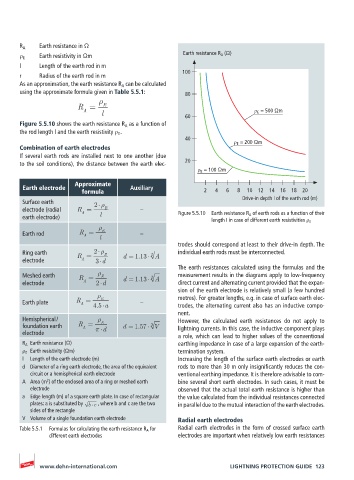
Figure 5.5.10 shows the earth resistance R A as a function of
the rod length l and the earth resistivity ρ E .
40
ρ E = 200 Ωm
Combination of earth electrodes
If several earth rods are installed next to one another (due
to the soil conditions), the distance between the earth elec- 20
ρ E = 100 Ωm
Approximate
Earth electrode Auxiliary
formula 2 4 6 8 10 12 14 16 18 20
Drive-in depth l of the earth rod (m)
Surface earth 2
electrode (radial R = E – Figure 5.5.10 Earth resistance R A of earth rods as a function of their
A
earth electrode) l
length I in case of different earth resistivities ρ E
Earth rod R = l E –
A
trodes should correspond at least to their drive-in depth. The
Ring earth R = 2 E d = 1.13 2 A individual earth rods must be interconnected.
electrode A 3 d
The earth resistances calculated using the formulas and the
Meshed earth R = E d = 1.13 2 A measurement results in the diagrams apply to low-frequency
electrode A 2 d direct current and alternating current provided that the expan-
sion of the earth electrode is relatively small (a few hundred
E
Earth plate R = 4.5 a – metres). For greater lengths, e.g. in case of surface earth elec-
A
trodes, the alternating current also has an inductive compo-
nent.
Hemispherical / E However, the calculated earth resistances do not apply to
foundation earth R = d d = 1.57 3 V lightning currents. In this case, the inductive component plays
A
electrode a role, which can lead to higher values of the conventional
R A Earth resistance (Ω) earthing impedance in case of a large expansion of the earth-
ρ E Earth resistivity (Ωm) termination system.
l Length of the earth electrode (m) Increasing the length of the surface earth electrodes or earth
d Diameter of a ring earth electrode, the area of the equivalent rods to more than 30 m only insignificantly reduces the con-
circuit or a hemispherical earth electrode ventional earthing impedance. It is therefore advisable to com-
2
A Area (m ) of the enclosed area of a ring or meshed earth bine several short earth electrodes. In such cases, it must be
electrode observed that the actual total earth resistance is higher than
a Edge length (m) of a square earth plate. In case of rectangular the value calculated from the individual resistances connected
plates: a is substituted by b c , where b and c are the two in parallel due to the mutual interaction of the earth electrodes.
sides of the rectangle
V Volume of a single foundation earth electrode Radial earth electrodes
Table 5.5.1 Formulas for calculating the earth resistance R A for Radial earth electrodes in the form of crossed surface earth
different earth electrodes electrodes are important when relatively low earth resistances
www.dehn-international.com LIGHTNING PROTECTION GUIDE 123