
Page 125 - 35_DS702_E_2014_Lightning_Protection_Guide
P. 125
Earth resistance R A (Ω) Voltage
%
14 ρ E = 200 Ωm 100
12 80
l = 10 m II
10 60
8 40
6 20
l = 25 m I
4
10 20 30 m
2 Distance from the
direction of cross centre point
0.5 1 1.5 measurement II
l Burial depth (m) 45 °
direction of side length 25 m
l = side length measurement I
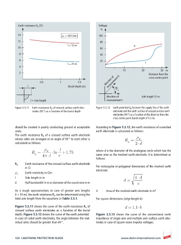
Figure 5.5.11 Earth resistance R A of crossed surface earth elec- Figure 5.5.12 Earth potential U E between the supply line of the earth
trodes (90 °) as a function of the burial depth electrode and the earth surface of crossed surface earth
electrodes (90 °) as a function of the distance from the
cross centre point (burial depth of 0.5 m)
should be created in poorly conducting ground at acceptable According to Figure 5.5.12, the earth resistance of a meshed
costs. earth electrode is calculated as follows:
The earth resistance R A of a crossed surface earth electrode
whose sides are arranged at an angle of 90 ° to each other is R = E
calculated as follows: A 2 d
l where d is the diameter of the analogous circle which has the
R = E ln +1.75
A 4 l r same area as the meshed earth electrode. It is determined as
follows:
R A Earth resistance of the crossed surface earth electrode
in Ω For rectangular or polygonal dimensions of the meshed earth
electrode:
ρ E Earth resistivity in Ωm
l Side length in m d = 4 A
d Half bandwidth in m or diameter of the round wire in m
As a rough approximation, in case of greater arm lengths A Area of the meshed earth electrode in m 2
(l > 10 m), the earth resistance R A can be determined using the
total arm length from the equations in Table 5.5.1. For square dimensions (edge length b):
Figure 5.5.11 shows the curve of the earth resistance R A of d = 1.1 b
crossed surface earth electrodes as a function of the burial
depth; Figure 5.5.12 shows the curve of the earth potential. Figure 5.5.13 shows the curve of the conventional earth
In case of radial earth electrodes, the angle between the indi- impedance of single-arm and multiple-arm surface earth elec-
vidual arms should be greater than 60 °. trodes in case of square-wave impulse voltages.
124 LIGHTNING PROTECTION GUIDE www.dehn-international.com